Composites have been widely used for years due to their unique properties, but their complexity makes failure analysis challenging. Engineers rely on various failure criteria like Hashin, Tsai-Wu, and Tsai-Hill to guide their designs. However, the Puck Failure Criterion offers a more refined approach by not only distinguishing between fiber and matrix failures but also identifying the exact fracture plane and different inter-fiber failure modes. This added detail helps engineers predict where and how damage starts, leading to more accurate failure analysis.
What is Puck Failure Criterion in simple terms?
The Puck failure criterion is a handy tool for analyzing fiber-reinforced composites. It helps us understand different types of failures in the matrix and fibers. This is especially important when creating high-performance structures, like wind turbine blades, where predicting failures accurately is crucial.
The Puck failure criterion can significantly enhance the design process for composite structures by providing a more detailed understanding of failure modes.
Pros:
- Demonstrates exceptional accuracy in predicting inter-fiber failures.
- Provides a thorough and in-depth analysis.
- Incorporating the Puck criterion into design considerations could lead to more innovative and resilient composite solutions. For instance, using this criterion allows for tailored designs that account for specific stress conditions and the unique properties of the composite materials being used. This means we can create structures that are not only lighter and stronger but also more reliable under varying loads.
Cons:
- Demands extensive material testing and meticulous parameter determination.
- Involves a complex and intricate implementation process.
- Additionally, by identifying potential failure points early in the design phase, we can implement preventative measures, such as reinforcing certain areas or adjusting the layup of fibers. This proactive approach ultimately leads to safer and more efficient composite structures, which is especially crucial in high-stakes applications like aerospace or wind energy.
In short, the Puck criterion plays a vital role in helping us understand and design better composite structures. It combines theory with practical application, making it a valuable resource for anyone working with advanced composite materials.
What types of failures does the Puck criterion help identify?
The Puck criterion primarily focuses on inter-fiber failures (IFF) and distinguishes between various fiber and matrix failure modes. This makes it a valuable resource for designers who need to ensure the reliability of composite materials in demanding applications.
At its heart, the Puck criterion offers a set of equations that address these various failure modes. It shines a light on how fibers and the spaces between them can fail in unidirectional composites, giving us a clearer picture of what’s happening inside the material.
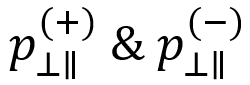
What’s really cool is that the Puck criterion breaks down fiber failures into two distinct modes, making our analysis even more detailed. To use this powerful tool effectively, we need to know two key things: the type of composite material—whether it’s carbon fiber reinforced polymer (CFRP) or glass fiber reinforced polymer (GFRP)—and some specific fiber properties, like the longitudinal modulus and Poisson ratio.
1. Fiber Failure
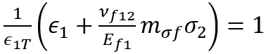
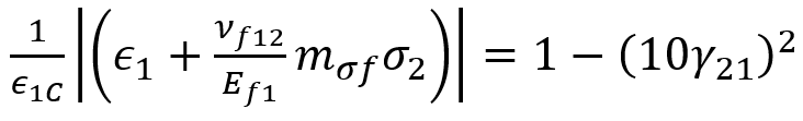
Within the framework of the Puck criterion, fiber failure manifests in two distinct modes: the initial mode pertains to tensile failure, while the subsequent mode involves compressive “fiber kinking” failure. The criteria for tensile fiber failure are as follows:
and the compressive “fiber kinking” failure is:
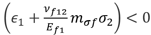
In the above equations, the tensile equation is evaluated if:
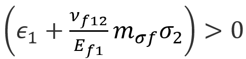
And the compressive criterion is evaluated if:
In the above fiber failure criteria:
| Composite strains corresponding to composite longitudinal tensile and compressive failure, respectively. | |
| Uniaxial strain in the composite. | |
| Longitudinal Poisson ratio of the fiber | |
| Longitudinal tensile modulus of the fiber | |
| Transverse stress of the composite | |
| Longitudinal shear strain in the composite | |
| Intended to capture the differences in the transverse stresses in the fiber and matrix. |
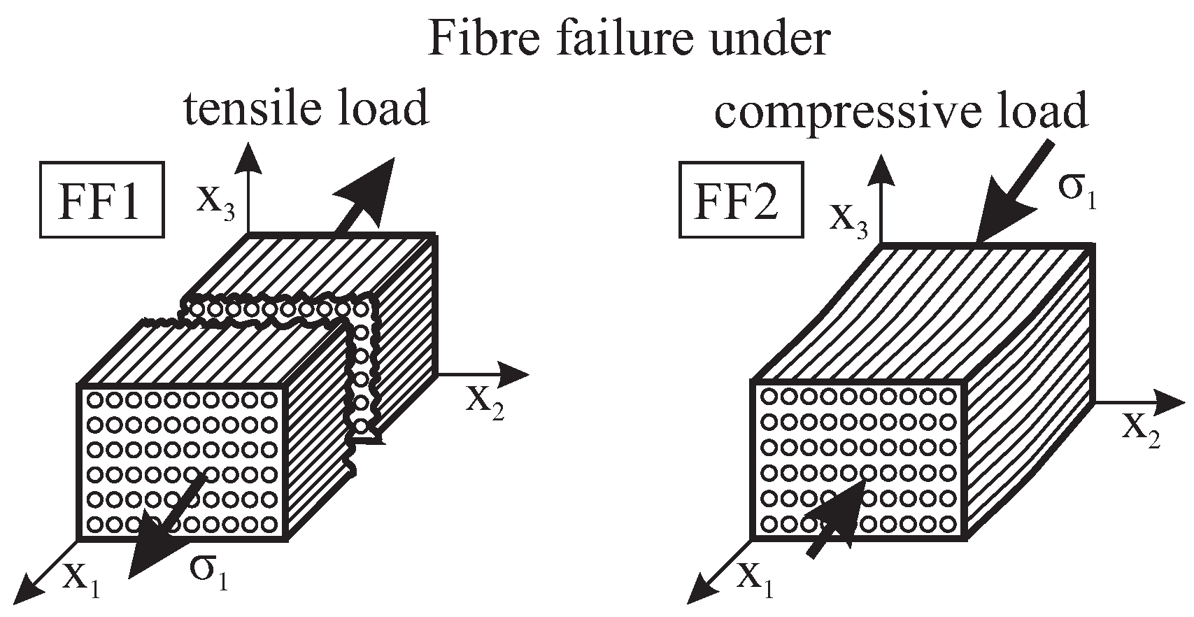
Figure 1: Fiber Failure under tension and compression [Ref]
2. Inter-Fiber Failure (Matrix Cracking)
Let’s dive into another part of the Puck failure criterion and talk about something really important: Inter-Fiber Failure, also known as Matrix Cracking. This failure mode plays a key role in keeping composite materials strong and reliable.
So, what’s happening here? Inter-fiber failure involves the cracking of the matrix material that sits between the fibers. This can have a big impact on how well the composite structures perform and how long they last. By closely examining Inter-Fiber Failure, the Puck criterion helps us understand how matrix cracking affects the mechanical behavior and failure mechanisms of fiber-reinforced composites.
Within the Puck framework, Inter-Fiber Failure includes any instances of matrix cracking or when fibers and the matrix start to separate. It breaks down into three distinct failure modes, which we call modes A, B, and C. These modes are identified based on how the fracture planes relate to the reinforcing fibers.
By exploring these concepts, we can better appreciate how to design and improve composite materials for various applications!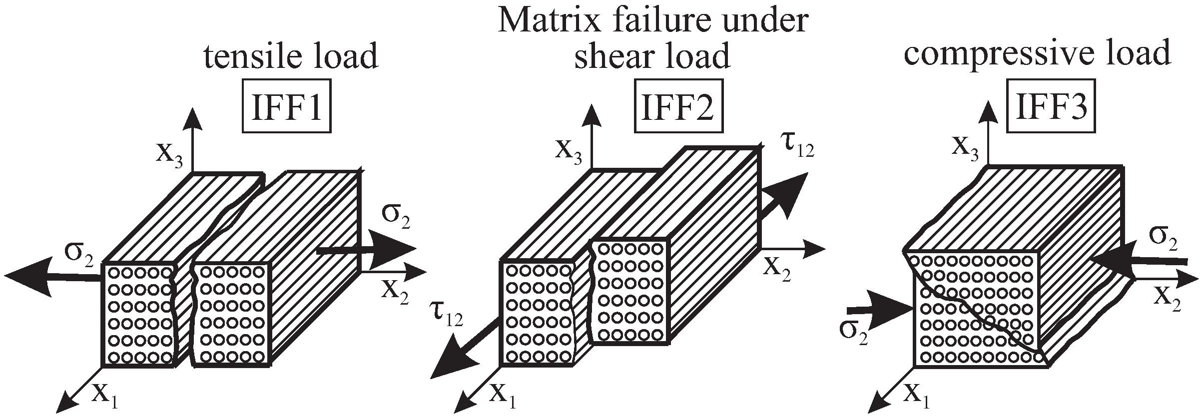
Figure 2: Matrix Failure under three loading conditions [Ref]
- Inter-Fiber Failure Mode A:
Mode A, characterized by a fracture angle of 0°, serves as a pivotal indicator of transverse stress surpassing 0 within the composite structure. This mode unveils itself through the emergence of a transverse crack perpendicular to the applied transverse loading, signifying a critical juncture in the structural response of the composite material.
- Inter-Fiber Failure Mode B:
Mode B unfolds within a realm where transverse compressive stress acts as a guardian against crack propagation, intertwining with longitudinal shear stress that falls below a predefined fracture resistance threshold. This mode, incorporating empirical constants for precise calculation, unravels the delicate interplay between compressive forces and shear stresses within the composite matrix.
- Inter-Fiber Failure Mode C:
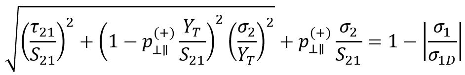
Mode C emerges as a realm where transverse compressive stress stands as a stalwart barrier to crack advancement, while substantial longitudinal shear stress emerges as a potent force capable of instigating fracture along an inclined plane relative to the fiber axis. The failure criterion for Mode C delves into the intricate balance of these opposing forces, delineating the thresholds for fracture initiation and propagation within the composite structure.
The above criterion is evaluated if:
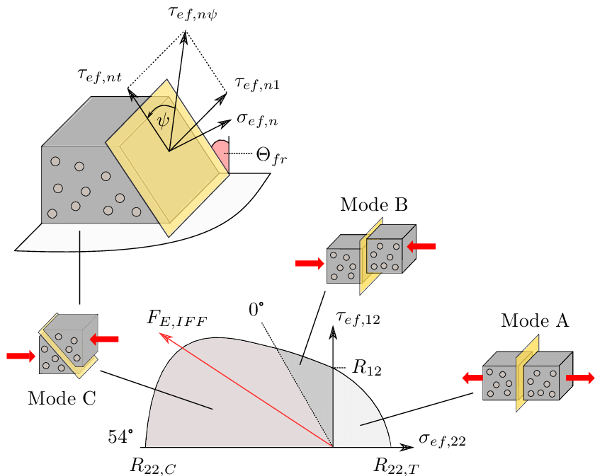
Figure 3: Inter-fiber failure modes [Ref]
| composite longitudinal shear stress | |
| composite longitudinal normal stress | |
| composite transverse normal stress | |
| composite transverse tensile strength | |
| composite transverse compressive strength | |
 |
slopes of the |
To establish the connection between ![]() and
and ![]() , Puck assumes the following relationship holds:
, Puck assumes the following relationship holds:
Therefore, ![]() is given by:
is given by:
Within the context of the in-plane stresses and strains of the Classical Laminate Theory, ![]() can be defined as
can be defined as ![]() which allows Puck to express
which allows Puck to express ![]() as:
as:
Now we must define the values for ![]() and
and ![]() . Puck and Mannigal (2007) provide the following recommended values for
. Puck and Mannigal (2007) provide the following recommended values for ![]() and
and ![]() .
.
| Reinforcement Type |  |
|
| Glass Fiber | 0.25 | 0.3 |
| Carbon Fiber | 0.3 | 0.35 |
Puck also defines ![]() as:
as:
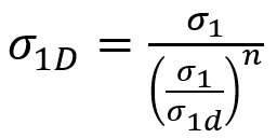
Finally, we must define ![]() . That is a “degraded” stress in the composite allowing for pre-fiber failure breakage of individual fibers, which causes localized damage in these areas in the form of microcracking and debonding. To account for this weakening effect, Puck degrades the fracture resistances (R) by a weakening factor
. That is a “degraded” stress in the composite allowing for pre-fiber failure breakage of individual fibers, which causes localized damage in these areas in the form of microcracking and debonding. To account for this weakening effect, Puck degrades the fracture resistances (R) by a weakening factor ![]() . Puck defines two equations for this. The first is for the generalized weakening factor.
. Puck defines two equations for this. The first is for the generalized weakening factor.
The second is to give another expression of the weakening factor in order to keep the fracture conditions homogeneous and of first-degree with respect to the stresses.
For the in-plane stress states considered by Simulation Composite Design, these two should be equal since there are no iterative calculations on fracture planes being performed. Therefore:
Based on the recommendations of Puck, Simulation Composite Design uses n=6 for the exponent and empirically computes ![]() as
as ![]() depending on the sign of
depending on the sign of ![]() .
.
To sum it all up, the Puck failure criterion is a fantastic tool that helps us understand inter-fiber failure modes, like matrix cracking and fiber-matrix debonding, in composite materials. By breaking these failure modes down into categories A, B, and C and setting clear criteria for each, the Puck criterion gives us valuable insights into how fiber-reinforced composites behave and fail.
This framework is super helpful for engineers and researchers as they work to optimize the design and performance of composite structures. Ultimately, it plays a big role in advancing material science and structural engineering. So, whether you’re designing new materials or improving existing ones, the Puck criterion is definitely something to keep in your toolkit!
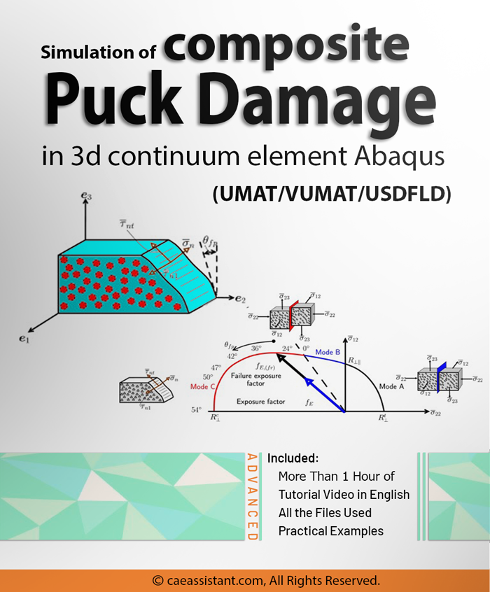
Comprehensive Guide for Applying the Puck Failure Criteria in ABAQUS
Designing with composite materials is challenging due to their complex failure behavior, but simulations can help reduce costs, speed up development, and improve safety. By applying the Puck Failure Criteria in Abaqus, we can accurately predict key failure modes like fiber breakage, matrix cracking, and delamination.
To simulate Puck in Abaqus, we use three subroutines: UMAT, VUMAT, and USDFLD—each with a specific role. This training covers the creation of a 3D continuum puck damage initiation model through the use of three subroutines. It is important to understand that once damage occurs, the model experiences a sudden loss of properties leading to failure. The focus of this training is on the Puck failure criterion.
UMAT is ideal for capturing complex, static material behavior and internal damage progression with detailed constitutive models, while VUMAT excels in dynamic analyses by accurately handling high-strain-rate events and large deformations. Meanwhile, USDFLD provides the extra advantage of explicitly tracking and outputting user-defined damage variables, giving us a clear picture of damage evolution that isn’t as easily extracted directly from UMAT or VUMAT alone.
Note that all the tutorials along with verified free-error files are available through our tutorial package; however, we’ll show you some of it in the following.
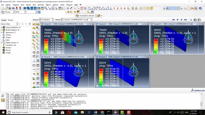
Simulation Process of Puck criteria in Abaqus
- In the following video, for Explicit and Standard analyses in Abaqus, the model is simulated only as a shell. However, with the help of subroutines, we were able to simulate the model in 3D.
- In all methods, mechanical properties and strengths are entered into the Property module. These properties are defined in the subroutine by props in this module. This comprehensive training series focuses on the simulation of composite PUCK damage in 3D continuum elements within ABAQUS for T700/epoxy.
- In this modeling, we considered the Tsai-Hill failure criterion for Explicit and Standard analyses, and for the subroutines, we considered the Puck criterion.
- The boundary conditions of the model are such that on one side, the model is fixed in all directions, and on the other side, a compressive force is applied to it by using displacement control.
- Results and verification: Finally, by comparing all five methods and observing the close proximity of the failure results, we realized that we can use these subroutines from now on to achieve more accurate results.
Detailed Breakdown of the Subroutines
UMAT
We’ll walk you through writing the UMAT subroutine line by line, so you’ll really get to know what each part does. By breaking it down into manageable pieces, we ensure that you’re not just memorizing code but truly understanding how it works.
- Purpose: The UMAT subroutine allows users to define custom material behaviors that are not available in standard libraries. This flexibility is essential for simulating the nonlinear behaviors typical of composite materials.
- Strengths: One of the significant advantages of UMAT is its ability to model complex stress-strain relationships. It can capture the unique responses of composites under various loading conditions, including different orientations of fibers.
Note: The formulas implemented in the subroutines for the Puck failure criteria are simplified and more practical compared to the detailed versions discussed earlier in the blog. They represent streamlined forms of the full equations, making them easier to work with in simulations.
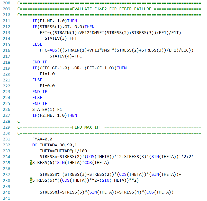
Figure 4: A part of the UMAT subroutine written for simulating the Puck criterion in a 3D model
VUMAT
But that’s not all! We also dive into the VUMAT subroutine for modeling puck theory, which is super versatile and can handle more complex material models, like viscoelasticity and damage evolution. You’ll learn how to validate the VUMAT subroutine with the Abaqus explicit solver, running simulations on composite materials and comparing your predictions against experimental data. This validation process is crucial and helps you build confidence in your modeling skills.
- Purpose: VUMAT is specifically designed for explicit dynamic analyses, making it suitable for high-strain rate events, such as impacts or explosive loading scenarios.
- Strengths: The primary advantage of VUMAT is its capability to handle dynamic interactions accurately. This allows for effective simulations of how composite materials respond to sudden loads, providing critical insights into their performance during extreme events.
USDFLD
And if that’s still not enough, we include the USDFLD subroutine for puck theory, where you’ll learn how to simulate the damage behavior of composites in detail. This subroutine allows you to define field variables that change over time, providing a dynamic view of how damage progresses under different loading conditions.
- Purpose: The USDFLD subroutine enables the incorporation of additional state variables into the material model. These variables can represent factors such as damage levels or other environmental influences.
- Strengths: USDFLD excels at tracking how these variables evolve throughout the simulation, providing insights into damage accumulation and its effects on material performance. By integrating these additional variables, we can enhance the accuracy of our simulations, especially in fatigue analyses where understanding the gradual degradation of materials is critical.
Different Failure Criteria in Composite Materials
In analyzing composite materials, it’s crucial to consider various types of failures to ensure that components remain strong and reliable. Here are some key failure modes commonly examined in composite analysis:
- Fiber Breakage
- Matrix Cracking
- Delamination
In the picture below, you can see different types of damage and failure modes in composites.
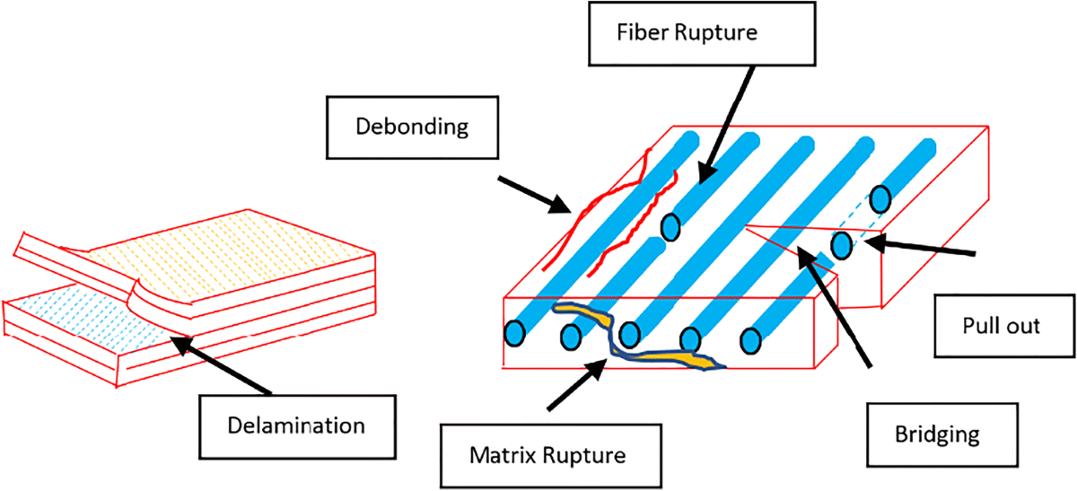
Figure 5: Different types of failure in composites [Ref]
When it comes to analyzing composite materials, designers have come up with several failure criteria to help predict and prevent issues with these complex materials. These guidelines are super helpful for ensuring that composite components remain strong and reliable.
In the diagram below, you can see the classification of composite failure criteria in one glance to understand them and the difference between them once and for all.
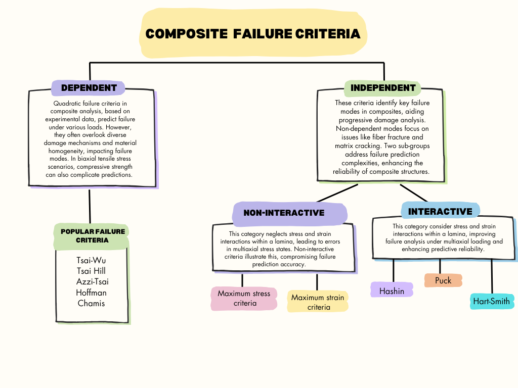
Figure 6: Composite Failure criteria
This training package is focused on simulating composite damage using Puck Failure Criterion in 3D continuum elements using UMAT, VUMAT, and USDFLD subroutines in Abaqus. It covers different types of failure in composites, including fiber failure, matrix cracking, delamination, and interfacial failure, as well as criteria for predicting failure modes in composites that are dependent or not dependent on each other. The package provides step-by-step guidance on simulating composite Puck theory using each of the subroutines mentioned above in Abaqus.