Fused Deposition Modeling process (FDM) is one of the most common methods in 3D printing, where thermoplastic material is melted and deposited layer by layer to create an object. FDM simulation is valuable for predicting how printed parts will behave under different conditions, allowing engineers to detect issues early and improve designs efficiently before production.
What is Fused Deposition Modeling Process in 3D printing?
Fused Deposition Modeling process (FDM) is a popular 3D printing technique that creates objects layer by layer by extruding thermoplastic materials through a heated nozzle. The nozzle traces each layer’s cross-section pattern, depositing material that solidifies upon cooling. FDM is widely used for its efficiency and adaptability with various materials, making it suitable for prototyping, functional parts, and complex geometries.
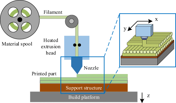
Figure 1: Fused Deposition Modeling process [Ref]
What is LDED method and the difference between FDM and LDED?
Laser Direct Energy Deposition (LDED) is another 3D printing method that differs from FDM primarily in its material handling. While FDM deposits material in a molten state through a heated nozzle, LDED injects powdered or wire-like raw material onto the build surface, where a laser heats it at the point of deposition. Thus, FDM heats before depositing, whereas LDED heats the material upon deposition, although the simulation process for both in Abaqus is largely similar.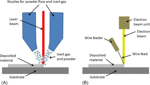
Figure 2: Laser Direct Energy Deposition LDED
How to begin FDM Simulation in Abaqus?
Let’s tackle a common question together: “How exactly is a 3D printing simulation done?” While the specifics may vary depending on the additive manufacturing simulation software, the basic principles are usually quite similar. Here, we’ll focus on Abaqus Additive Manufacturing, a widely-used platform for simulating 3D printing processes, particularly in FDM (Fused Deposition Modeling).
To start a 3D printing simulation in Abaqus, your model must first be designed, either in a CAD program or directly within Abaqus’s FEM (Finite Element Method) environment. The model is then segmented into thin layers, each representing a slice of material that the printer will deposit. Once layered, these slices are imported into Abaqus, where you can define the essential conditions for FDM, including material property variations, boundary constraints, and thermal settings.
In FDM simulations, the process involves a sequential thermomechanical analysis. This means that thermal effects are modeled first, followed by structural analysis to capture how the material stabilizes after deposition. By applying Abaqus’s unique settings for FDM, such as defining event series, material deposition, and cooling, you can create an accurate, layer-by-layer simulation of the printing process.
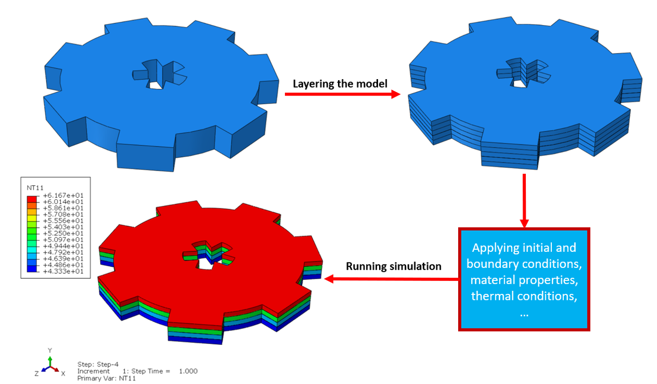
Figure 3: How to begin 3D printing simulation in Abaqus
What are the inputs we need for FDM Simulation?
The basic inputs required for FDM simulation include the model geometry (e.g., the substrate and the printed object), material properties, and the event series that defines the nozzle path and speed. Additionally, specific boundary conditions and initial temperatures must be set to accurately simulate the printing process and subsequent cooling.
What is Bead and its relation with the layers of the model?
In FDM, each printed path of material is called a “bead.” Beads stack in a defined path to form layers that, in turn, build up the 3D model. For example, if each bead has a height of 0.9 mm, the layer’s thickness also equals 0.9 mm, with the number of layers depending on the model’s overall height. The beads can have circular or rectangular cross-sections based on model requirements.
You can better understand that with another example. Suppose we want to print this block with the FDM method (see fig 4). The tiny circular bars pile up to form the block. We would call each of these tiny bars the “bead”. The length of each bead is the length of the block. The bead height is parallel to the stack direction, and the bead width is perpendicular.
If the bead height and width equal 2 millimeters, the bead cross section would be two times two millimeters; the thickness of each layer would be 2 millimeters because of the bead height, and the number of layers equals 3 because the total thickness of the model is 6 and 2 times 3 equals 6; and there will be 6 beads in each layer because the total width of the block is 12 and 6 times 2 equals 12 (see fig 4).
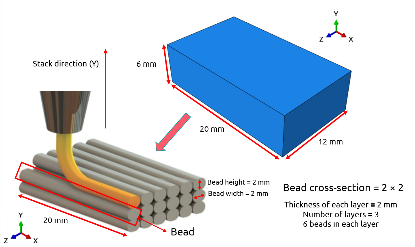
Figure 4: bead and the layers of the model
Note: The figure above is directly from the FDM workshop which you can access to the complete version of it through this link.
The bead relation with the mesh size of the model
In FDM simulations, the relationship between bead dimensions and mesh size is critical for accuracy. Each bead, the individual path of deposited material, contains several elements, influencing both the layer thickness and the precision of the final model. For instance, in the example given, a bead height of 0.9 mm dictates that each layer’s thickness will also be 0.9 mm, ensuring alignment between physical deposition and simulated layers.
Here’s how it works: if the bead width is divided into four elements, each element width must align with the bead’s width dimension in the model’s cross-section. The mesh elements should fit into each bead in a way that represents the physical structure realistically. For example, in the attached tutorial, a bead with a 3.35 mm width is modeled with a cross-section containing four elements, each measuring approximately 0.838 mm across. This approach ensures that every time a layer is added in the simulation, the model activates one new element, creating an accurate, layer-by-layer structure.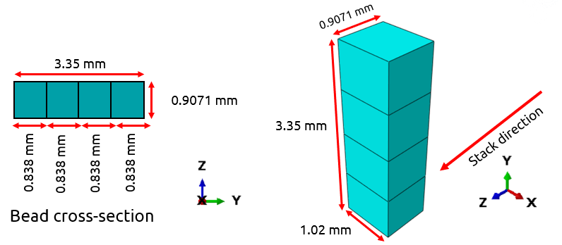
Figure 5: Bead and Mesh size
Note: the meshing in the FDM simulation in Abaqus is very important and it’s just not mesh with a good mesh size wich is aquired through mesh convergence. See more details in our workshop.

Event series and nozzle’s speed in FDM simulation
The event series in Abaqus specifies the nozzle’s location over time in X, Y, and Z directions. This dataset also controls the nozzle speed, impacting material deposition and heat distribution. For example, the travel speed might be 5.22 mm per second, with power settings for the heater defined within the series. Accurately configuring the event series is crucial for simulating the material flow and heating processes in FDM.
Introduction to AM Modeler Plug-in
The AM Modeler Plug-in in Abaqus enables streamlined simulations for additive manufacturing (AM) processes like FDM. This tool offers options for defining event series, material inputs, and heat sources. Let’s explore some of its core functionalities.
Basic info about Event series
The event series in the AM Modeler Plug-in is essential for directing material deposition and defining heat sources. This data includes the nozzle’s location at specific times and its power output, allowing for accurate simulation of material flow and temperature distribution across layers.
Basic info about material input (Material Deposition & Element Activation)
In the AM Modeler Plug-in, the Material Input section is vital to define how materials behave and are applied throughout the simulation. This involves two main areas:
1- Material Deposition: This part controls how each bead of material is deposited. Within the plug-in, you can choose “Bead” or “Roller” as the deposition method. The “Bead” setting replicates the layer-by-layer buildup by depositing each individual bead in a specified path, following the design’s cross-section. With this setting, each bead must be modeled separately, requiring precise input on dimensions like height and width to match the real-world deposition process. The “Roller” option, in contrast, deposits an entire layer at once, which is more suitable for processes like powder-bed fusion but less accurate for FDM.
2- Element Activation: This setting determines how and when elements are activated during simulation. In FDM, progressive element activation matches each layer deposition sequence. The simulation activates elements as the nozzle moves along its path, making this process mirror actual printing by activating only the elements within each new bead path. Proper element activation is essential to avoid inaccuracies in temperature distribution and mechanical behavior across layers.
3.3. Basic info about moving heat source
In FDM simulation, heat sources apply energy to each bead, influencing its cooling and solidification. The AM Modeler offers three heat source distribution options:
- Concentrated: This heat source focuses energy at a single point, simulating an intense, localized heat effect, ideal for small, specific areas.
- Uniform: Distributes energy evenly within a defined area, simulating a broader heating effect that covers an entire layer or zone.
- Goldak: A 3D energy distribution that follows an exponential decay pattern, creating a more natural heat spread. This method captures the gradual cooling and heat dissipation typical in 3D printing.
Selecting the right heat source in your simulation is essential for capturing the thermal dynamics during FDM printing accurately. Each method allows for fine-tuning heat application to achieve realistic cooling and bonding effects between layers.
Basic info about cooling
The cooling function in AM Modeler applies convection and radiation settings to simulate how each printed layer cools after deposition. Cooling rates affect thermal stress, making this setting crucial for an accurate FDM simulation.
Conclusion
In this article, we explored Fused Deposition Modeling (FDM) simulation, a core process in additive manufacturing where materials are deposited layer by layer. We looked at how this technique works and how it can be modeled using simulation tools like Abaqus.
Simulating FDM matters because it helps you predict things like temperature changes, warping, and stress—all before printing anything. This means fewer failed prints and better results, especially when precision is key.
We started with the basics of how FDM works. Then we broke down why simulation is helpful, especially for understanding how heat and material behavior affect the print. After that, we got into how you can simulate FDM in Abaqus, including heat flow, material properties, and key setup steps. Finally, we pointed out what kind of results you can expect from the simulation, like temperature distribution and part deformation.
By the end, you now have a full picture of how FDM simulation works and how you can apply it in Abaqus to improve your 3D printing projects with confidence.