Modal analysis is a way to find out how something vibrates. Every object has its own natural way of shaking when it’s pushed or disturbed. Modal analysis helps engineers figure out those natural vibration patterns so they can design things that don’t fail or shake too much when forces act on them. When the vibration of a structure matches its natural frequency, it can lead to serious damage or even collapse. That’s why it’s important to understand these behaviors before building anything.
In this blog, we’ll start by what is modal analysis and showing why it matters for structural safety and performance. Then, we’ll explore its applications in different fields with real-world examples. Next, we’ll walk through the key concepts—natural frequency, damping, and mode shapes—before diving into how to carry out an Abaqus modal analysis. We’ll also go through a practical example with a cantilever beam, share tips for improving accuracy, and discuss common challenges and how Abaqus helps address them. By the end, you’ll understand how modal analysis works, why it’s important, and how to apply it using modern simulation tools. One major trend is the use of data-driven and machine-learning-assisted modal analysis is also discussed in this post.

What is Modal Analysis?
A clear and concise definition of modal analysis:
This analysis assists engineers in comprehending the vibrational behavior of a structure when subjected to free vibration conditions, in the absence of any external forces. Modal analysis is a computational technique used to determine the dynamic characteristics of a structure or mechanical system such as natural frequencies, mode shapes, and damping. These characteristics define how a structure vibrates under dynamic conditions and are essential for understanding its dynamic behavior.
Importance of Modal Analysis in Structural Dynamics
Understanding the dynamic behavior of structures is critical for ensuring their performance, safety, and longevity. Modal analysis helps identify potential resonance issues, which can lead to catastrophic failures if not addressed.
When the frequency of an external force aligns with one of the system’s natural frequencies, a phenomenon referred to as resonance takes place, resulting in the system experiencing excessively large oscillations. The failure of structures such as buildings, bridges, turbines, and airplane wings has been linked to the occurrence of resonance. As depicted in Figure 1, when the frequency of the applied load (represented on the x-axis) approaches the resonant frequency, the amplitude of the response (shown on the y-axis) tends toward infinity.
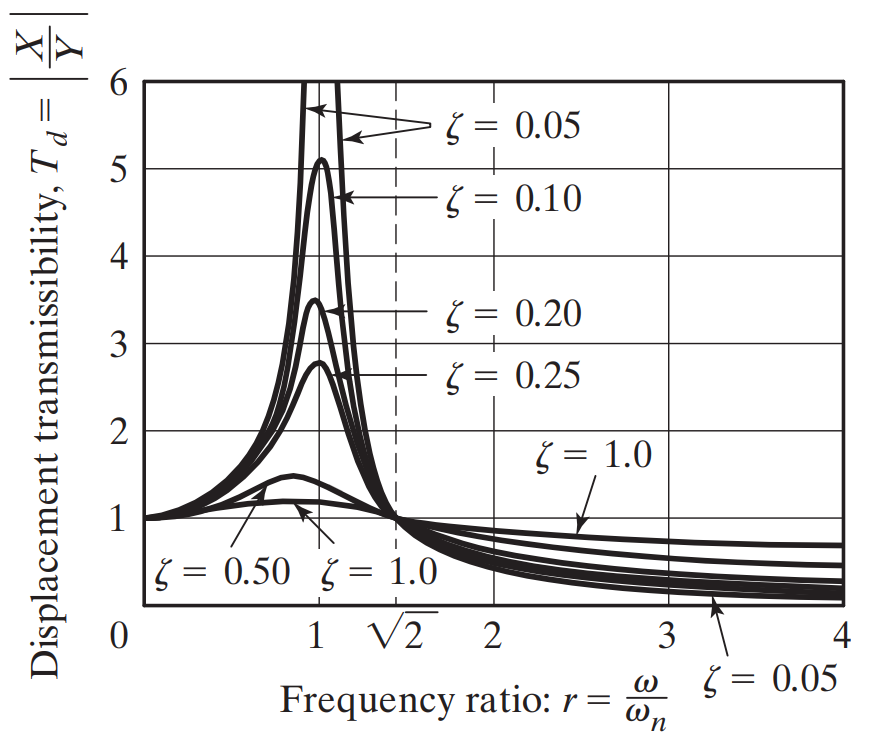
Figure 1: Amplitude of response versus the frequency ratio
Additionally, modal analysis aids in optimizing designs to achieve desired vibrational characteristics, thereby enhancing the overall reliability of structures. For example, in industries like aerospace or automotive engineering, lack of attention to vibrational modes can result in reduced operational efficiency, noise, and structural damage. Hence, modal analysis is a cornerstone of robust engineering practices.
In practice, modal analysis helps engineers identify potential issues before they manifest in real-world scenarios. For example, designing a bridge involves calculating its natural frequencies to ensure that pedestrian or vehicular loads won’t excite resonant vibrations. Similarly, in automotive design, modal analysis allows for tuning suspension systems to provide a smoother ride and better handling.
Applications of Modal Analysis
Engineering Fields Benefiting from Modal Analysis
Modal analysis has broad applications across various engineering disciplines, including:
- Aerospace Engineering: Ensuring structural stability and vibrational compatibility in aircraft and spacecraft.
- Automotive Engineering: Designing quieter and more durable vehicles by addressing vibrations in engines, chassis, and suspension systems.
- Civil Engineering: Assessing vibrational responses of bridges, buildings, and other infrastructure to external forces like wind or earthquakes.
- Electronics: Evaluating the dynamic performance of sensitive electronic components such as sensors and actuators.
Real-world examples: Aerospace, Automotive, Civil Engineering, and More
- Aerospace: Aircraft wings undergo modal analysis to prevent flutter; A dangerous phenomenon where aerodynamic forces amplify structural vibrations.
- Automotive: Engineers use modal analysis to optimize engine mount designs, reducing vibrations that impact comfort and performance.
- Civil Engineering: Modal analysis is applied to skyscrapers to ensure they can withstand seismic and wind-induced vibrations without structural failure.
The Mexico City Earthquake of 1985 is one of the real-world examples of modal analysis in which a prior accurate modal analysis could have averted the loss of lives and property. The resulting resonance with the lakebed frequency caused an earthquake. In other words, the resonant frequency of structures ranging from 6 to 15 stories closely matched the frequency of the earthquake (See figure 2).

Figure 2: An apartment building destroyed by Mexico City earthquake in 1985 [Ref]
The Tacoma Narrows Bridge was constructed in the state of Washington, United States. On November 7, 1940, at approximately 11 a.m., the bridge collapsed suddenly as shown in figure 3. Subsequent investigations determined that the failure was due to aeroelastic flutter.

Figure 3: Collapse of the Tacoma Narrows Bridge [Ref]
- Biomechanics: Prosthetic limbs and implants are analyzed to mimic the natural vibrational behavior of biological structures.
What Are the Key Concepts in Modal Analysis?
The key concepts of modal analysis are:
- natural frequency,
- damping,
- and mode shapes
which are explained and read in the following.
Natural frequency: What it is and why it matters
Frequency refers to the quantity of waves that traverse a specific point within one second. The unit of frequency is termed hertz (Hz), in honor of the German physicist Heinrich Hertz, who was the first to validate the existence of electromagnetic waves. Various formulas exist for calculating frequency, contingent upon the specific quantities that are known.
The formula for frequency can be expressed in several ways,
Formula 1: The frequency formula in terms of time is given as:
where,
- f denotes the frequency in hertz (Hertz=s-1)
- T represents the duration required to complete one cycle in seconds.
Formula 2: The frequency formula in terms of wavelength and wave speed is articulated as,
where,
- 𝜈 signifies the wave speed in m/s
- λ indicates the wavelength of the wave in meters.
Formula 3: Frequency expressed in terms of angular frequency is defined as,
where ω represents the angular frequency.
The angular frequency formula in a simple harmonic modal analysis (no damping) is ![]() which k is stiffness (or spring constant) and m denotes the mass of the object. Also, the frequency of vibration is achieved from
which k is stiffness (or spring constant) and m denotes the mass of the object. Also, the frequency of vibration is achieved from ![]() .
.
An object’s natural frequency is the frequency or rate at which it vibrates naturally when subjected to disturbance. Objects can possess more than one natural frequency and we typically use harmonic oscillators as a tool for modeling the natural frequency of a particular object.
Natural frequencies are the intrinsic vibrational frequencies of a structure. When a system is excited at these frequencies, resonance occurs, leading to amplified vibrations that can cause severe damage. Avoiding or controlling resonance is a primary objective in structural design.
Damping: Types of damping and its role in system behavior
Damping mechanisms dissipate vibrational energy, reducing the amplitude of oscillations. The primary types of damping are:
- Viscous Damping: Energy is dissipated proportionally to velocity.
- Structural Damping: Energy dissipation occurs through internal material friction.
- Hysteretic Damping: Associated with cyclic stress-strain relationships in materials.
Effective damping design ensures that structures return to equilibrium quickly after being subjected to dynamic forces.
Mode shapes: Visualization and interpretation
Mode shapes are the deformation patterns of a structure corresponding to its natural frequencies. Visualizing mode shapes provides insights into which parts of a structure experience the most significant displacement during vibration. This information is crucial for optimizing geometry and material distribution.
How these concepts relate to vibrations and resonance
The interplay between natural frequencies, damping, and mode shapes defines a system’s dynamic behavior. By understanding these parameters, engineers can design structures that remain stable and efficient under operational conditions.
Steps to Perform Abaqus Modal Analysis
Abaqus is one of the most widely used software for modal analysis simulation. Modal Analysis in Abaqus involves the computation of eigenvalues (natural frequencies) and eigenvectors (mode shapes) of a structure, which are derived from the mass, stiffness, and damping characteristics of the finite element model. The outcomes of this analysis can be represented visually in Abaqus through mode shapes and frequency tables.
In the next section we will have a step by step example; but if you like you can get our full tutorial of modal analysis with more examples.
Preprocessing the Model
- Import or create the geometry of the structure in Abaqus.
- Define material properties, such as Young’s modulus, density, and Poisson’s ratio.
- Apply appropriate boundary conditions to simulate real-world constraints.
- Mesh the structure, ensuring that the element size captures the necessary details of the geometry while maintaining computational efficiency.
Setting Up the Modal Analysis Step
- Choose the “Frequency” analysis step in Abaqus.
- Specify the number of modes to extract, typically focusing on the first few modes as they have the most significant impact on structural behavior.
- Configure solver settings to ensure convergence and accuracy.
Running the Simulation
- Submit the analysis job and monitor progress in the Abaqus environment.
- Address any issues, such as convergence errors, by refining mesh settings or adjusting boundary conditions.
Postprocessing and Interpreting Results
- Use visualization tools in Abaqus to examine mode shapes and frequencies.
- Interpret the results to identify critical frequencies and assess the system’s vibrational behavior.
Practical Example: Abaqus Modal Analysis (Eigenvalue problem)
In this section, a practical example will be explained for a better understanding of modal analysis.
Modal analysis solves eigenvalue problems to calculate the natural frequencies and associated mode shapes of a system. These problems form the mathematical foundation of the analysis.
A Walkthrough of a Simple Model (e.g., A Cantilever Beam)
In this section, a simple example will be explained to learn how to simulate modal analysis in Abaqus. Consider a cantilever beam as shown in figure 4.
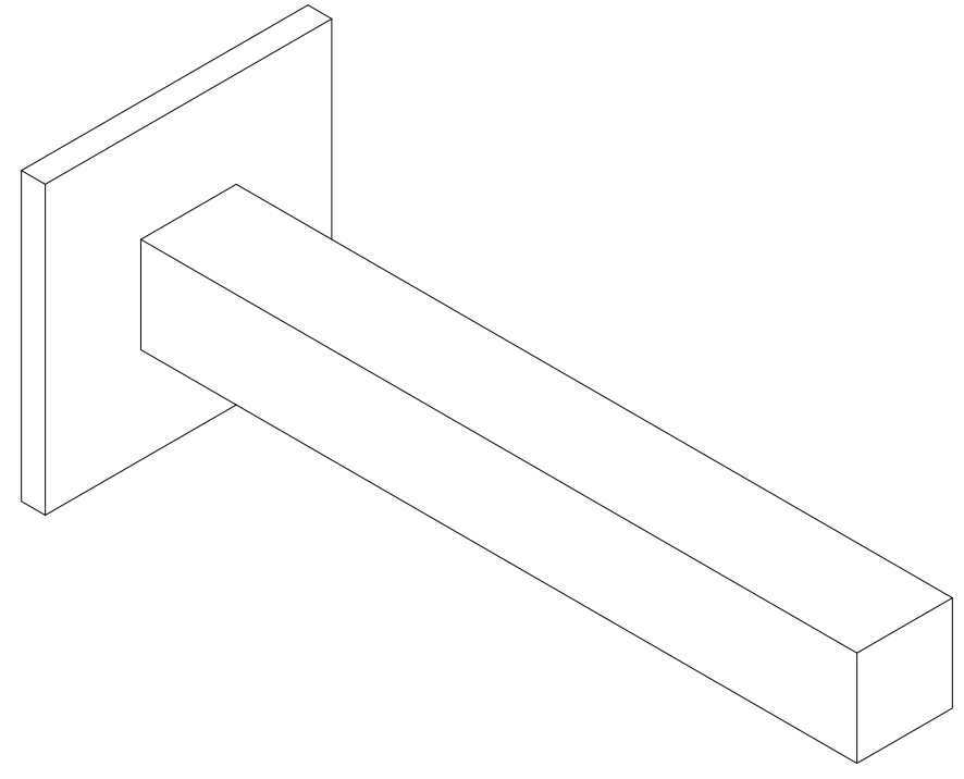
Figure 4: A cantilever beam
1. Model Creation: Define the geometry of a cantilever beam in Abaqus. Figure 5 shows a model of a cantilever beam in Abaqus (Length=0.1m, Width=0.1m, Depth=1m).
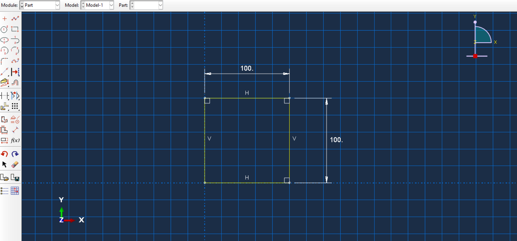
(a) |
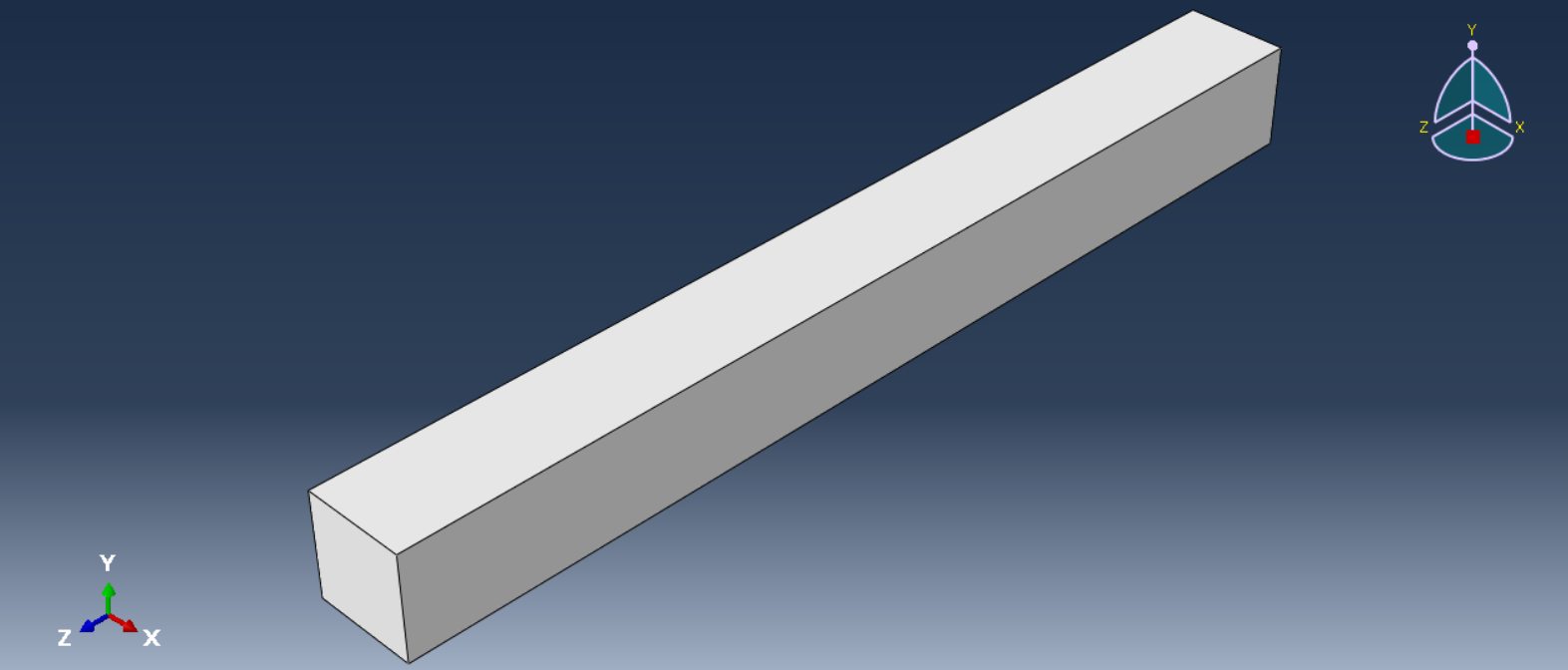
(b) |
Figure 5: A cantilever beam (a) cross-section sketch (b) isometric view
2. Material Properties: Assign properties such as steel’s density (7850 kg/m³) and Young’s modulus (210 GPa) (See figure 6).
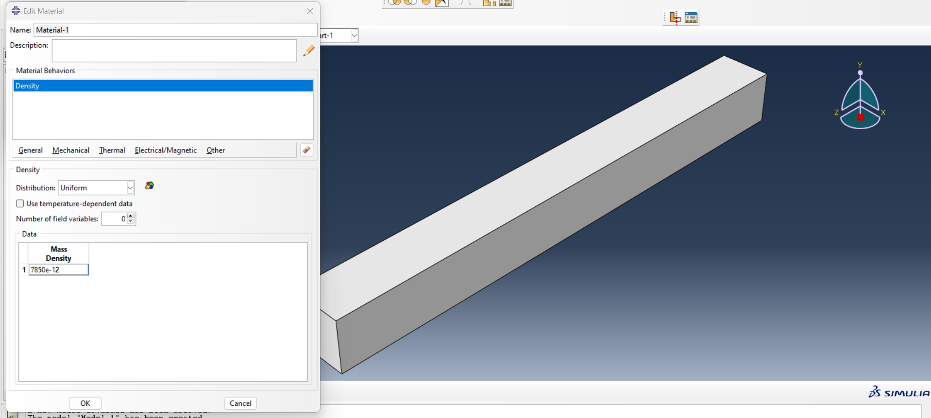 |
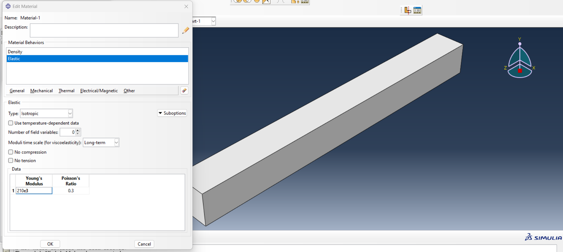 |
Figure 6: Assign material properties
3. Create Step: Defines the type of analysis as a linear perturbation for eigenvalue extraction (modal analysis). The Frequency command is used to control the number of eigenvalues to be computed, and it defines how the solver will approach the frequency extraction (See figure 7). Also, defining the number of eigenvalues means the number of natural frequencies as shown in figure 8.
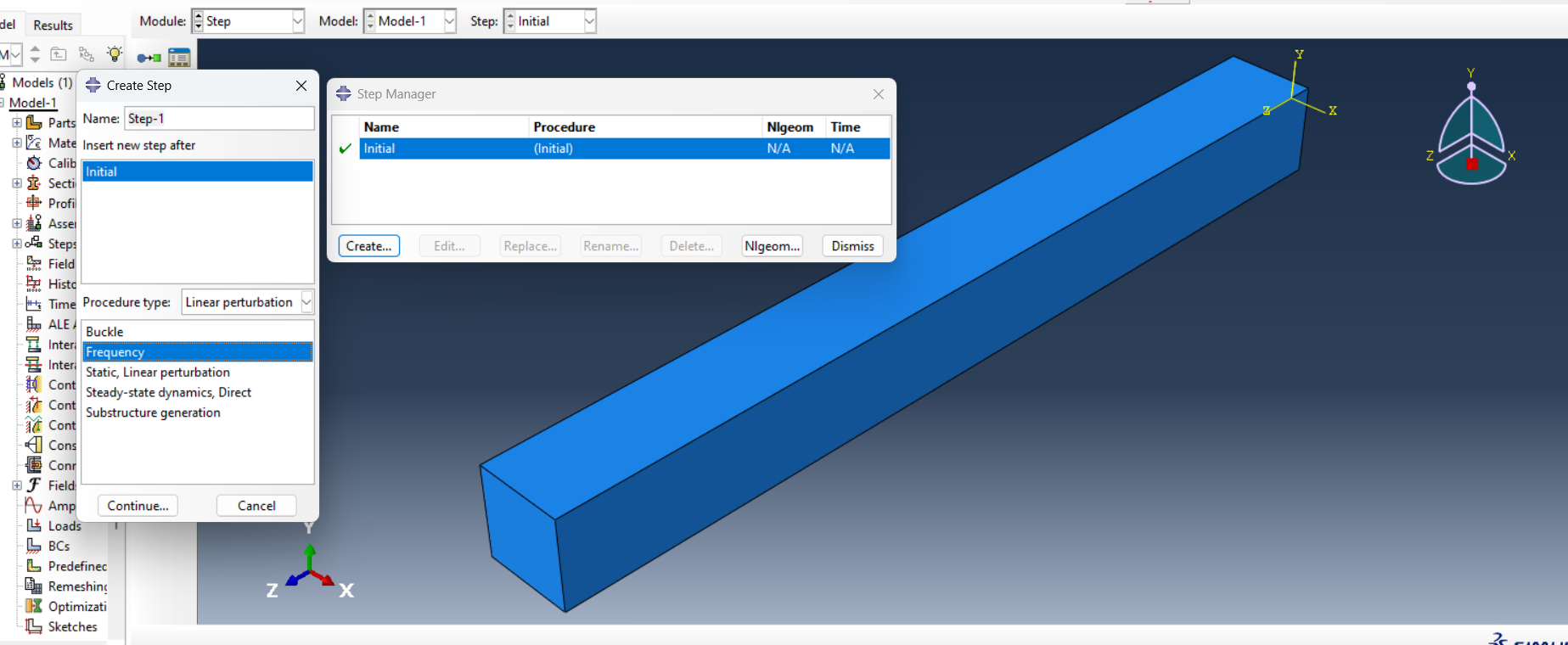
Figure 7: Step for modal analysis
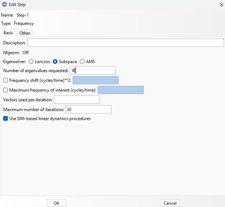
Figure 8: Define the number of eigenvalues
4. Boundary Conditions: Apply boundary conditions so that one end is fixed and the other free to move to simulate a cantilever beam, as illustrated in figure 9.
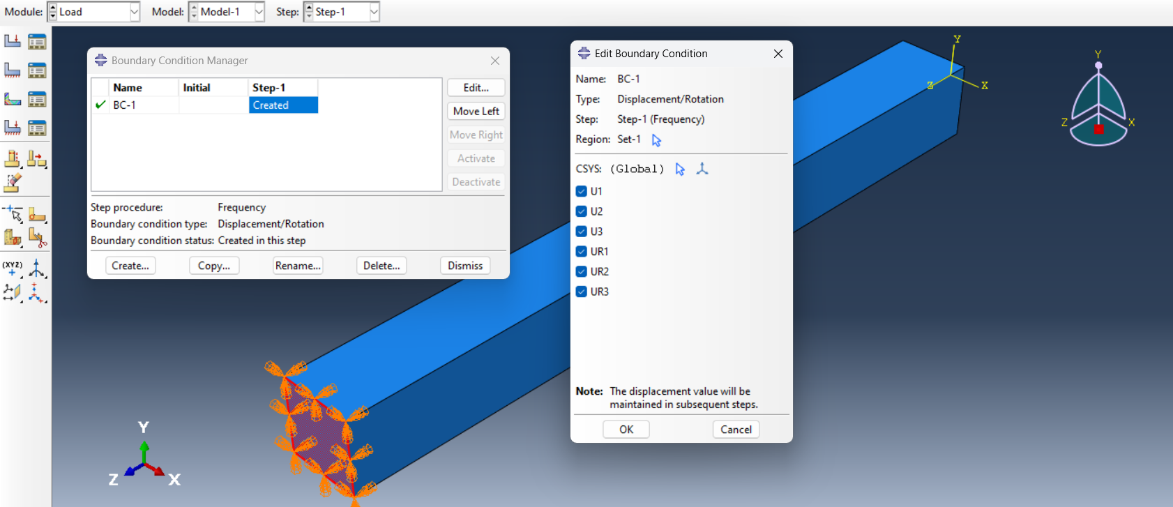
Figure 9: Boundary conditions
5. Meshing: Use a fine mesh to capture the beam’s vibrational behavior accurately (See figure 10).
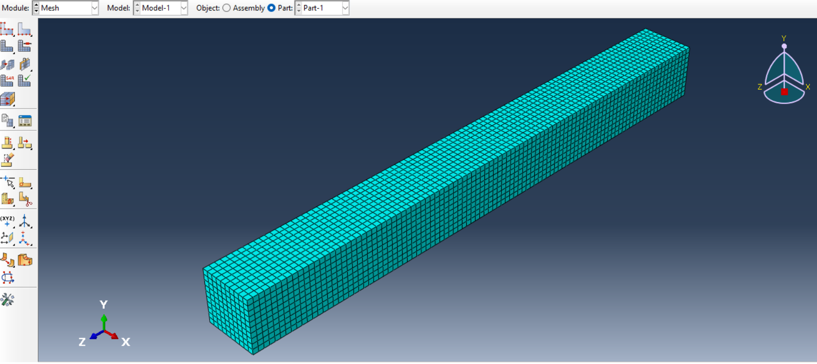
Figure 10: Meshing
6. Frequency Analysis: Run the simulation to extract natural frequencies and mode shapes. Visualization of natural frequencies and mode shapes for the first three modes of the cantilever beam is presented in figures below.
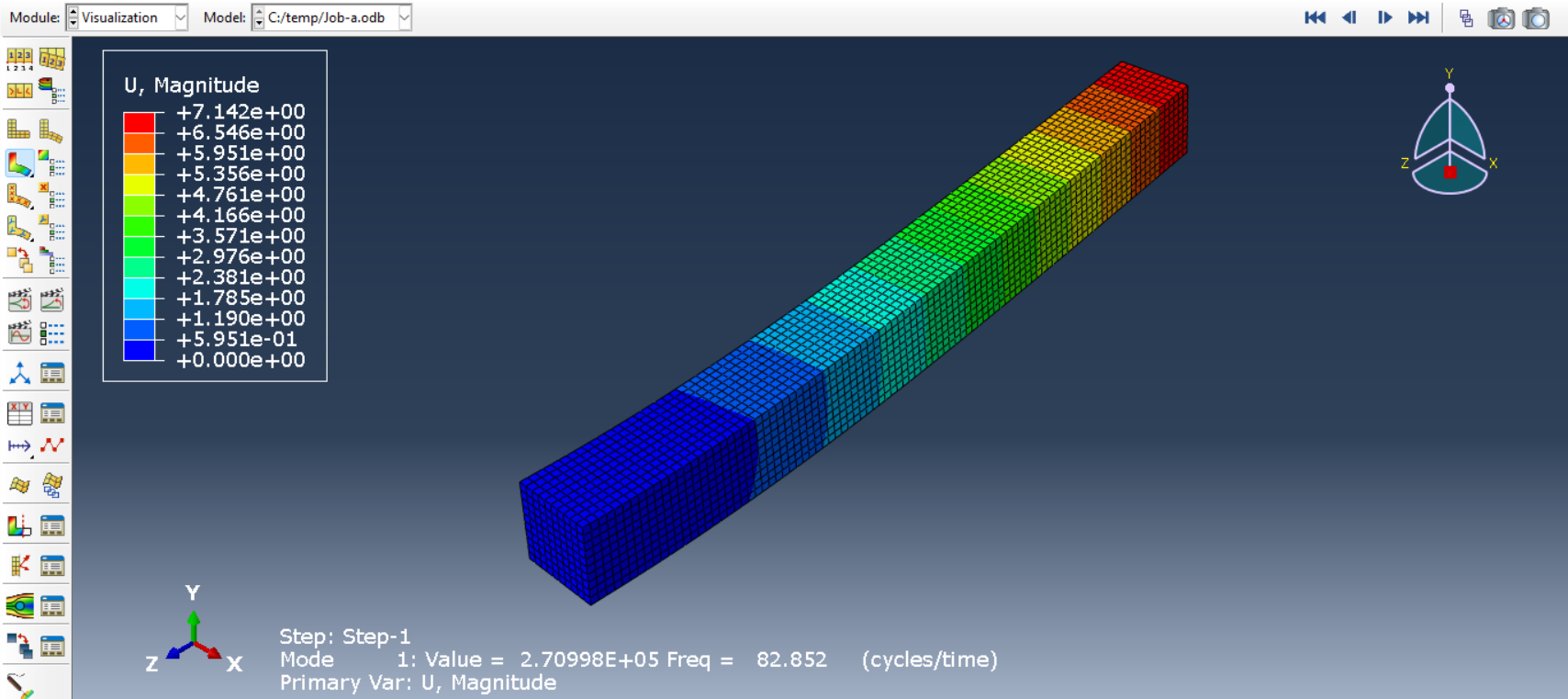
Figure 11: First mode shape
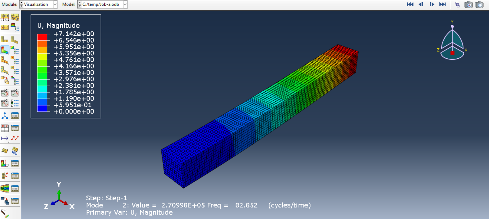
Figure 12: Second mode shape
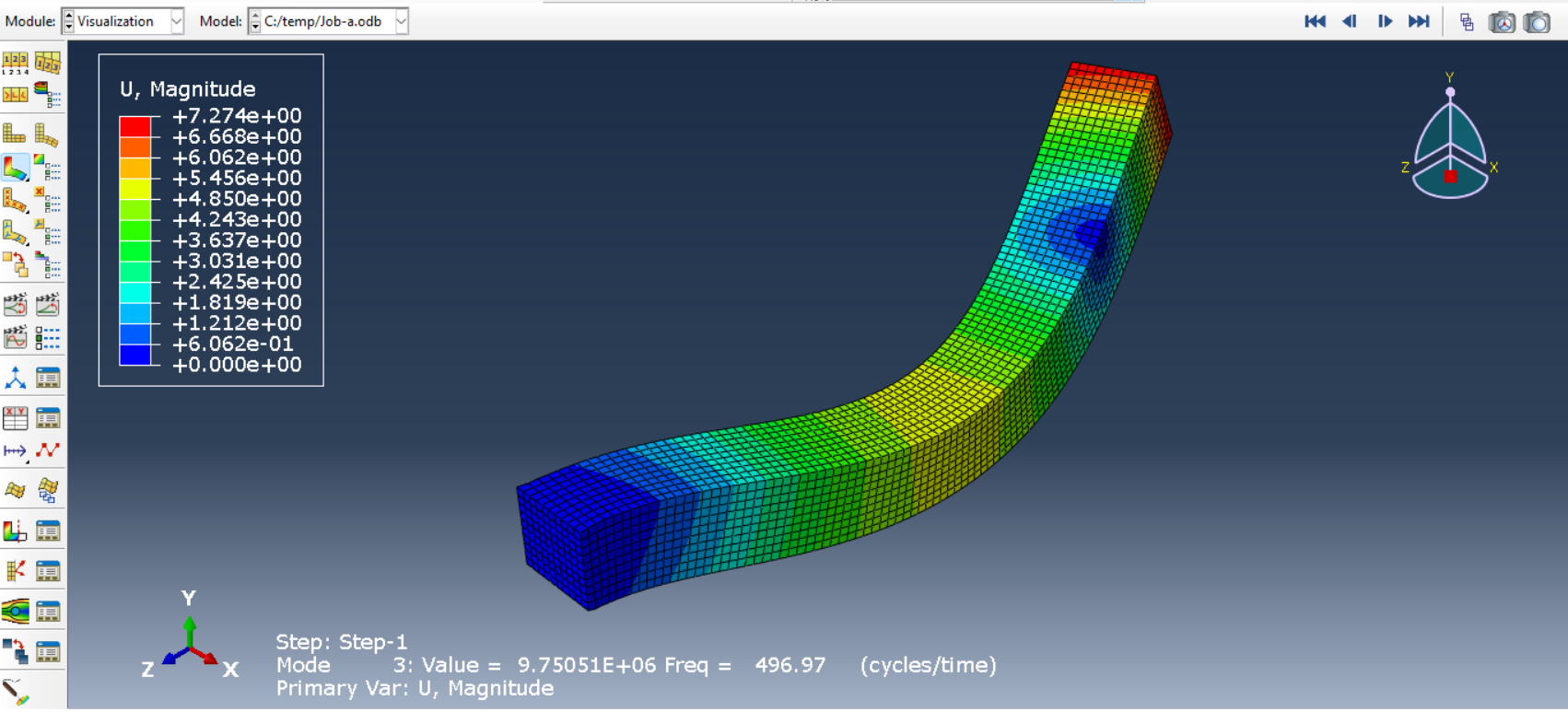
Figure 13: Third mode shape
Visualizing and Understanding Mode Shapes
You can examine the results to discern patterns of deformation. For example, the initial mode shape generally features the beam undergoing bending, whereas the subsequent modes display more intricate patterns, such as twisting or the presence of multiple bending points.
Tips for Accurate Modal Analysis
Ensuring Mesh Quality and Refinement
- Use finer mesh sizes in regions of high-stress gradients or complex geometry.
- Perform a convergence study by running the analysis with varying mesh densities and comparing results.
Handling Convergence Issues
- Verify that boundary conditions are applied correctly and realistically.
- Adjust iteration tolerances or use a higher-order element type for improved accuracy.
Challenges and Solutions in Modal Analysis
Common Issues Faced During Analysis
- Mesh Quality: Poorly defined meshes can lead to inaccurate results or convergence errors.
- Boundary Conditions: Incorrect or unrealistic constraints can distort the analysis.
- Solver Errors: Inadequate solver settings may result in non-convergence or incorrect eigenvalue extraction.
How Abaqus Helps Overcome These Challenges
- Robust Solvers: The solvers of Abaqus are designed to handle complex eigenvalue problems efficiently.
- Diagnostic Tools: Built-in tools help identify and resolve issues in model setup and simulation.
- Comprehensive Documentation: Abaqus provides detailed guides and tutorials to assist users in overcoming common challenges.
Trends and Recent Advances in Modal Analysis (2025–2026)
In the field of modal analysis, recent research and industry tools have started to push the boundaries beyond classical eigenvalue-based vibration analysis. One active area is the integration of machine learning and data-driven methods with traditional finite element models. Researchers are using artificial neural networks (ANNs) to enhance operational modal analysis by automating model updating based on experimental vibration data. These neural approaches can reduce uncertainties in both experimental and computational models, enabling more reliable modal parameter estimation across varying conditions and structural types.
In simple terms, these methods use measured vibration data—such as accelerometer signals—to help identify or refine modal parameters. Instead of manually tuning a finite element model to match experimental results, algorithms can learn the relationship between model parameters and measured dynamic responses. For beginners, it is helpful to think of this as an automated form of model updating that reduces human trial-and-error rather than replacing physics-based analysis.
Another significant trend is the development of reduced-order and surrogate models for dynamic systems. These methods, including parametric reduced-order models, aim to drastically cut computational cost while preserving essential dynamic characteristics, making them valuable for design optimization and real-time applications in geometrically nonlinear structures. High-fidelity finite element models can contain millions of degrees of freedom, making repeated modal analyses computationally expensive. Reduced-order models aim to preserve the dominant modal characteristics while drastically lowering computational cost.
A third emerging area is advanced operational modal analysis (OMA). Unlike classical modal testing, OMA extracts modal properties from structures under real operating conditions, without requiring controlled excitation. Recent research combines OMA with physics-informed algorithms to improve robustness in noisy or incomplete data scenarios—an increasingly common challenge in modern monitoring systems.[/vc_column_text][/vc_column]
On the industry software side, AI-assisted tools like Simcenter Testlab’s new modal dashboard are accelerating the modal analysis workflow by automating stable pole selection and accelerating validation, reducing manual iteration while maintaining high accuracy.
Together, these developments hint at a future where modal analysis is not just a static eigenvalue problem but a dynamic, automated, and data-informed process that bridges simulation, experimentation, and real-time diagnostics
Key Learning Keywords and Search Phrases
For readers starting out, the following keywords are effective entry points for finding high-quality tutorials, papers, and courses:
- Modal analysis fundamentals
- Eigenvalue problem in structural dynamics
- Operational modal analysis (OMA)
- Finite element model updating
- Reduced-order modeling in dynamics
- Data-driven modal analysis
- Physics-informed machine learning for vibrations
- Experimental vs numerical modal analysis
These keywords help bridge classical vibration theory with modern computational and data-driven approaches, forming a solid roadmap for learning contemporary modal analysis.
Conclusion
To summarize, we have examined the concepts of modal analysis, including natural frequencies, damping, and mode shapes, while demonstrating practical applications through software like Abaqus. Additionally, it outlined the steps involved in performing modal analysis, offered tips for accurate simulations, and addressed common challenges, showcasing how Abaqus helps overcome these obstacles. Through real-world examples, the blog highlighted the importance of modal analysis in creating robust and reliable engineering solutions. Finally, it was found that modal analysis is a vital tool for engineers across industries, enabling them to evaluate and enhance the vibrational behavior of structures. Abaqus offers advanced capabilities for accurate and efficient modal analysis, making it an invaluable resource for solving dynamic problems. By leveraging Abaqus, engineers can ensure the safety, reliability, and performance of their designs, addressing even the most complex dynamic challenges with confidence.