Before reading the article “engineering applications of finite element method”, you can read the first part of article of finite element analysis applications: “10 Useful Abaqus Subroutine part-1”
Finite Element Analysis Applications | Engineering applications of finite element method
When you want to simulate an analysis in the ABAQUS, you may encounter some complications that require user-defined coding. So, ABAQUS has left you a coding platform for this matter. It’s called the ABAQUS subroutine. Here, we have presented some Abaqus user subroutine examples. We explained some of them with finite element analysis applications in engineering.
Finite element analysis (FEA) is widely used across various industries for design optimization, structural analysis, thermal analysis, fluid flow simulations, and more. In the automotive industry, FEA helps analyze vehicle crashworthiness, optimize component designs for weight reduction, and study aerodynamics.[1][4] The aerospace industry relies on FEA for aircraft structural integrity analysis, wing design optimization, and studying airflow patterns.[1] FEA is also crucial in civil engineering for analyzing the structural behavior of buildings, bridges, and other infrastructure under various loading conditions.[4] The manufacturing sector uses FEA to simulate and optimize manufacturing processes like metal forming and molding.[1][5] finite element analysis applications are fully discussed.
1. FRIC & VFRIC
When the extended versions of the classical Coulomb friction model provided in the ABAQUS can no longer help you with your related problem, and when you need a complex definition of shear transmission between contacting surfaces, these two could come in handy. In other words, if you need contact with user-defined friction, the FRIC (standard solver) or VFRIC (explicit solver) subroutine can be used.
Some FRIC & VFRIC instances
Pile foundation
In 2020, the Geotechnical and Structural Engineering Research Center at Shandong University of China investigated on a finite element analysis with the ABAQUS subroutine that predicts the pile groups’ response to individual piles’ different layouts in pile groups. The FRIC subroutine was developed as the secondary platform, a hyperbolic model of end resistance, and a softening model of skin friction for the contact pair calculation of the ABAQUS.
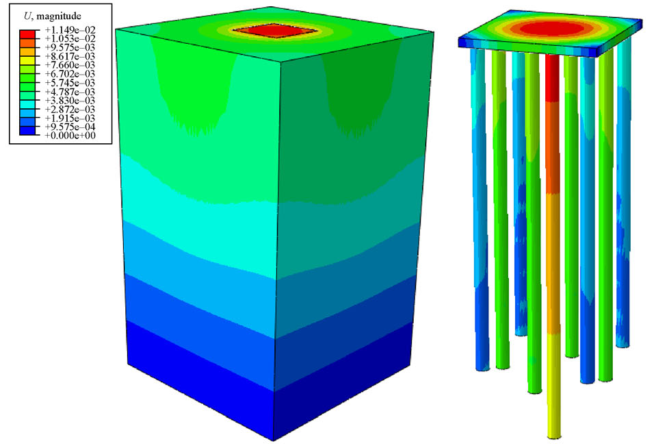
Figure 1: Response of a pile group under the total load of 6400KN [Ref]
Subsea pipelines
The submarine pipelines are mostly used to transport Oil and Gas.
In 2019, the School of Civil Engineering University of Tehran developed research about the local buckling of subsea pipelines. A model was simulated by the ABAQUS software and FRIC subroutine that can eliminate the walking occurrence. The pipe-soil interaction model was implemented by the FRIC subroutine, which controls the lateral and axial movement of the pipeline.
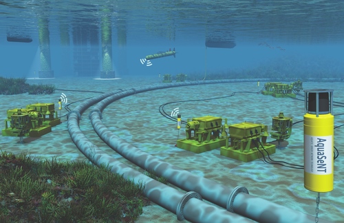
Figure 2: Subsea pipelines
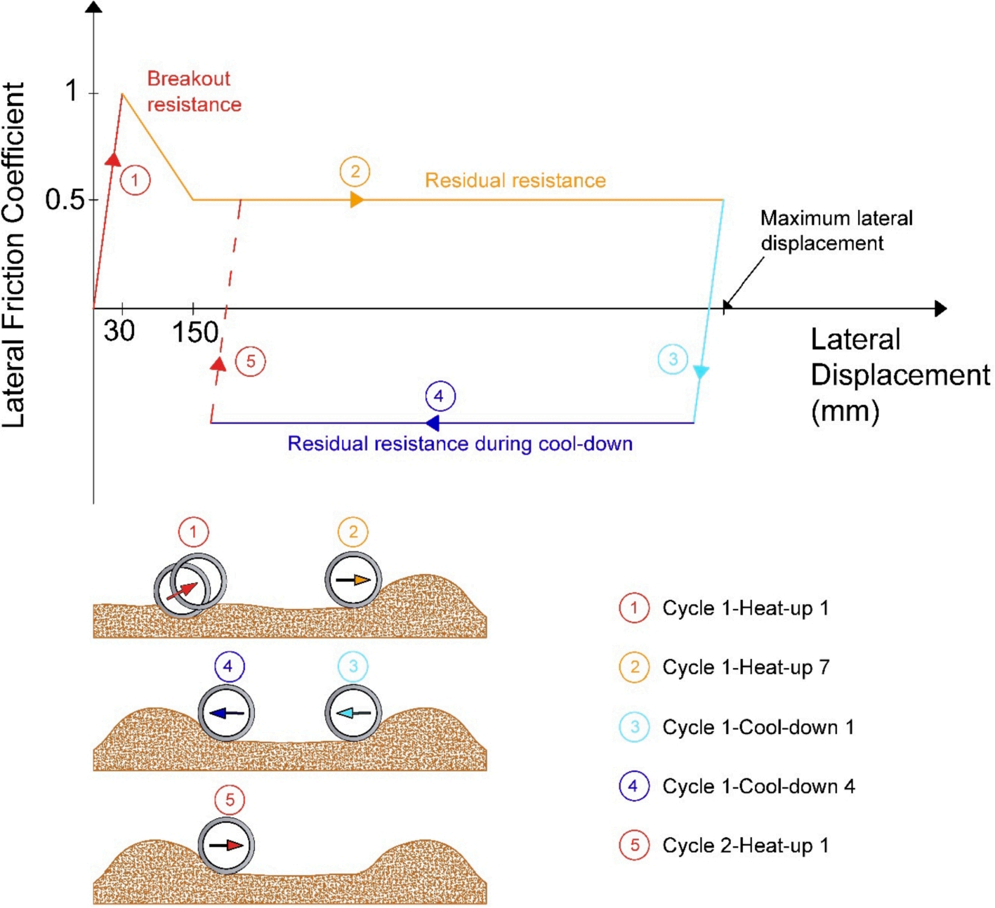
Figure 3: Cyclic pipe-soil interaction response during lateral displacements [Ref]
Tire- asphalt pavement contact behavior
In 2020, the National Science Foundation of China funded an investigation about tire-pavement contact behaviors under dry conditions. The researchers used the ABAQUS software to simulate a 3D finite element model to analyze these behaviors. Also, they used the FRIC subroutine to define the contact between the tire and the asphalt pavement. finite element analysis applications
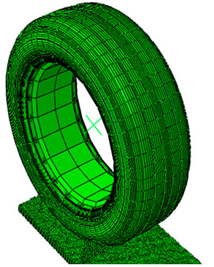
Figure 4: Simulation of the Tire-asphalt pavement contact [Ref]

Figure 5: Tire tracks on asphalt
Metal cutting modeling of titanium alloy
Titanium alloys are hard metals. They are used in many industries, such as aerospace, automotive, etc. Machining these alloys is a challenging process.
In 2011, China Scholarship Council (CSC) supported research to evaluate stress and damage during the cutting process. The researchers simulated a titanium alloy cutting with the help of the ABAQUS subroutine. The VFRIC subroutine developed an improved friction model and an orthogonal cutting model.

Figure 6: Cutting process simulation [Ref]
Note: If you want to learn more about this useful subroutine and see some examples, check this course:

2. UMESHMOTION subroutine
If you want to define motion for mesh nodes, you must use the UMESHMOTION subroutine. This subroutine helps you to specify Mesh Motion constraints during adaptive meshing. This subroutine is called at the end of any increment where adaptive meshing is performed. Engineering applications of finite element method in the UMESHMOTION subroutine are described below.
Engineering applications of finite element method for the UMESHMOTION subroutine
Artificial knee joints
Department of Mechanical Engineering University of Tokyo in 2020 worked on wear simulation of artificial knee joints. The investigators used the ABAQUS software and UMESHMOTION subroutine to evaluate the wear of artificial joints. The UMESHMOTION subroutine was used to update the geometry of the contact area. This is the important Abaqus user subroutine example.
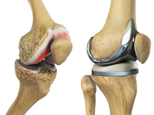
Figure 7: Total knee replacement
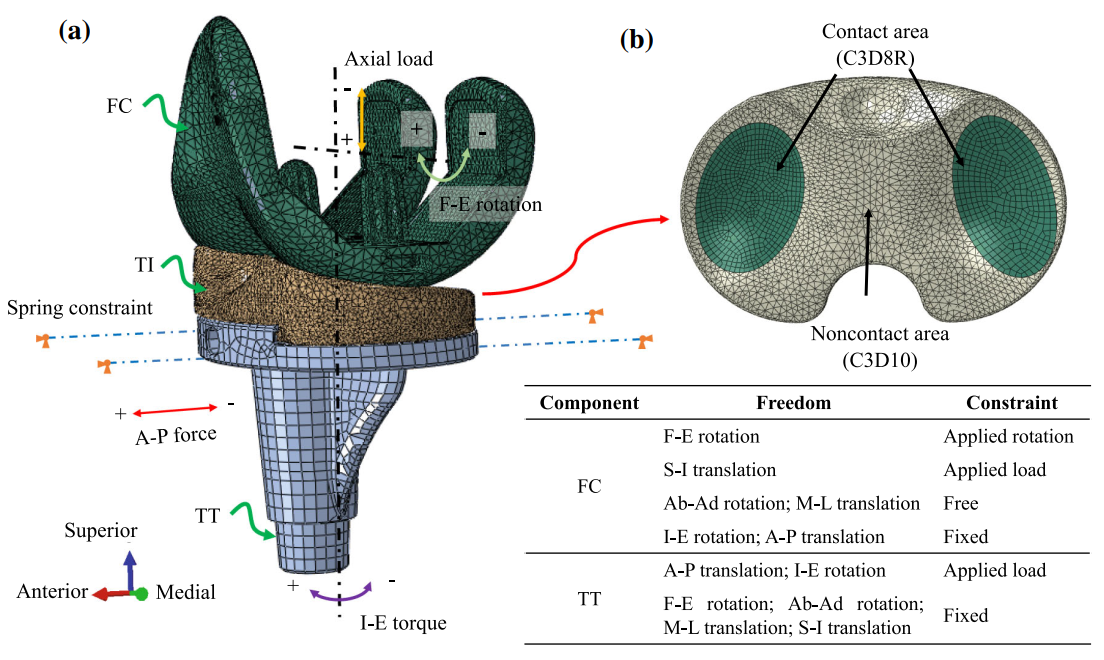
Figure 8: Simulation of total knee replacement [Ref]
Subroutine writing plays a crucial role in the finite element modeling and analysis of artificial knee joints, enabling researchers and engineers to accurately simulate and optimize the design and performance of these implants. Here are some key applications of subroutine writing in this field.
User-defined subroutines can also be developed to model the failure and damage mechanisms that may occur in artificial knee joints, such as wear, delamination, fatigue cracking, or loosening of the implant-bone interface. These subroutines can incorporate advanced damage models, fracture mechanics principles, and experimental data to predict the long-term performance and durability of the implant. By leveraging subroutine writing capabilities, researchers and engineers can create highly accurate and customized finite element models that capture the intricate details of artificial knee joint designs, materials, and loading conditions. These models can be used for design optimization, pre-clinical testing, and patient-specific simulations, ultimately leading to improved implant performance, longevity, and patient outcomes.
Fretting wear
In 2020, China Scholarship Council funded an investigation about Fretting wear finite element analysis under variable coefficient of friction. The fretting wear may cause losing fasteners or other problems; moreover, it is challenging to measure micromotion in experiments; So, FEM simulation and the ABAQUS subroutine can analyze its behavior. The UMESHMOTION subroutine executed the continuous change of the contact surface geometry.
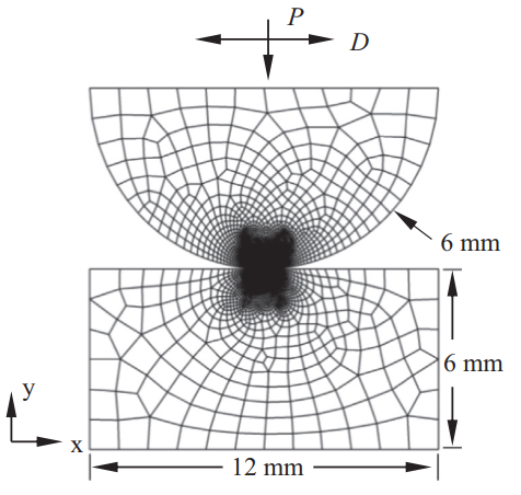
Figure 9: Dimensions and geometry of the basic model [Ref]
Note: You’re interested in this complicated yet very useful subroutine?! Want to see some examples? Click on this section:
3. HETVAL subroutine
This subroutine provides internal heat generation during heat transfer analysis. For instance, it could be associated with phase changes occurring during the solution. This subroutine could depend on state variables such as the fraction of material transformed.
HETVAL applications
Phase-field fracture method
The Phase-field method is a common technique to simulate crack initiation, propagation, and coalescence without the need to trace the fracture surface.
Department of Construction and Manufacturing Engineering University of Oviedo in 2021 presented a robust and simple application of the phase-field fracture method in the ABAQUS software with the HETVAL subroutine. With this method, you can use the ABAQUS’ in-built features and bypass the need for defining user elements. The HETVAL subroutine defined the internal heat flux and its derivative with respect to the temperature.
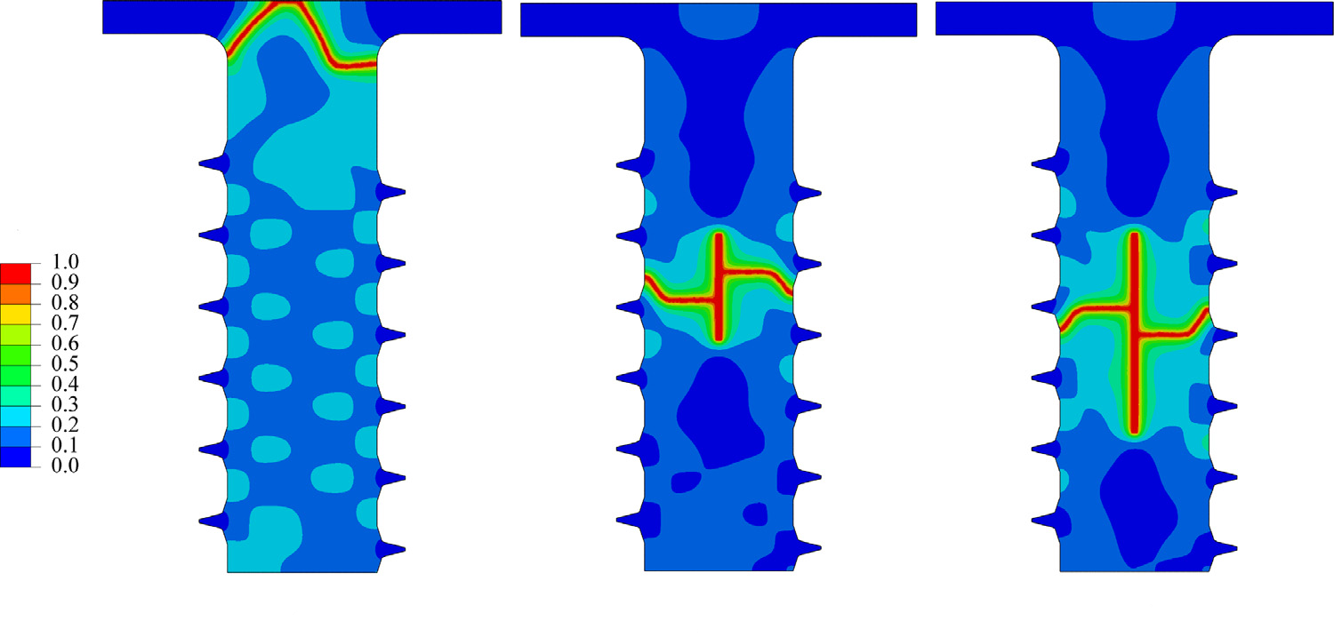
Figure 10: Final Phase-field contours for screw tension tests [Ref]
Rolling tire
In 2018, Korea Automotive Technology Institute developed a simulation method on a dynamic rolling tire to predict temperature rise. The investigators used the ABAQUS subroutine for the simulation. The HETVAL subroutine calculated the heat generation rate using total dissipated strain energy. With this Abaqus user subroutine example, you can make better designs.
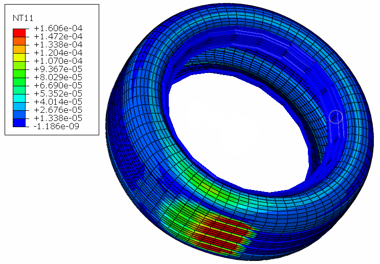
Figure 11: Rolling tire temperature distribution [Ref]
Carbon-Carbon composites
ASME congress in 2015 disseminated research that predicts the influence of thermal shock conditions on C/C composites. The researchers worked on this investigation with the help of the ABAQUS subroutines, the HETVAL and UMAT. The HETVAL subroutine implemented the generated internal heat caused by the carbon material degradation.
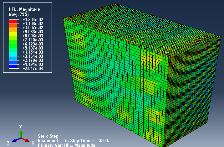
Figure 12: Heat flux distribution within the C/C composite [Ref]
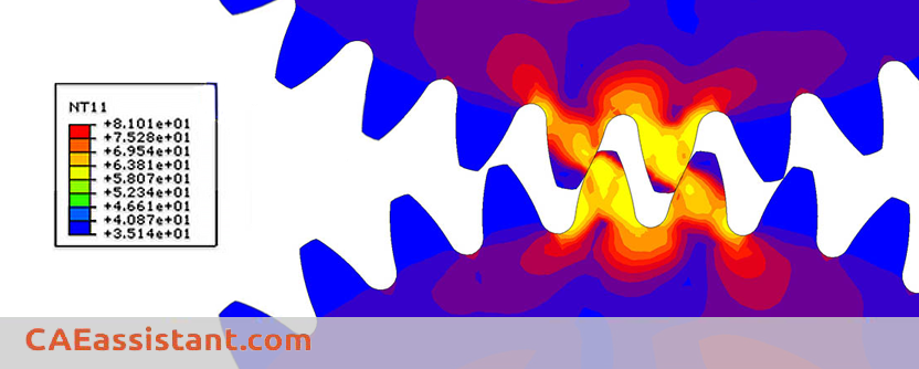
P91 steel welding
National Key Research and Development Program of China in 2021 supported an investigation that found a method to calculate the welding residual Stress of P91 steel. They used ABAQUS subroutines such as the HETVAL to achieve this method. The HETVAL subroutine developed the phase transformation latent heat generated by the martensite transformation.
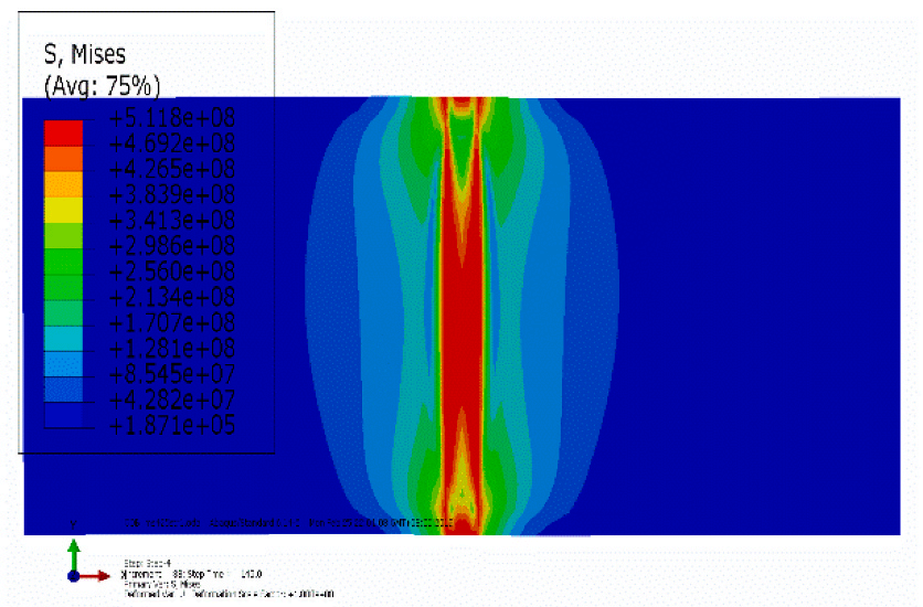
Figure 13: Stress distribution of one of the cases in the welding process [Ref]
I hope you enjoyed engineering applications of finite element method in the mentioned subroutines.
4. DFLUX subroutine
This subroutine can be used to define nonuniformly distributed flux in a mass diffusion or heat transfer analysis. It can be defined as a function of time, position, temperature, integration point number, element number, etc.
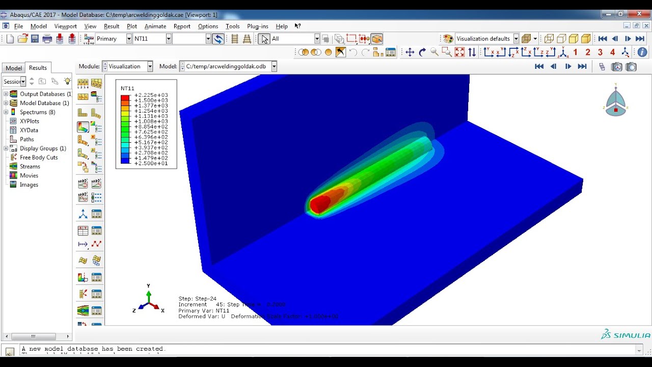
Figure 14: Arc welding simulation using DFLUX
Several applications of the DFLUX subroutine
Asphalt pavement
In 2018, the Dalian University of Technology in China developed a simulation to observe the Asphalt pavement behavior under cyclic temperature when a reflective crack is applied. The researchers used the ABAQUS subroutines such as the DFLUX and FILM. The DFLUX subroutine calculated the temperature distribution in the pavement structure. This is just one instance of this Abaqus user subroutine example. You can search and find many of them in the web.
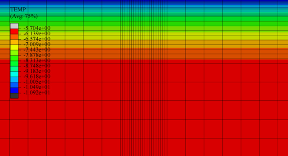
Figure 15: Temperature distribution in asphalt pavement structure [Ref]
Finite element modeling (FEM) has become an integral tool for civil engineers in simulating and analyzing the behavior of asphalt pavements. FEM allows researchers and practitioners to model the complex material properties, loading conditions, and structural interactions within pavement systems, providing valuable insights for design optimization and performance evaluation.
Key Applications of FEM in Asphalt Pavement Analysis
- Structural Response Analysis: FEM is widely used to predict critical pavement responses, such as stresses, strains, and deflections, under various loading scenarios, including static and dynamic loads. This information is crucial for assessing the potential for distresses like fatigue cracking and rutting.
- Material Characterization: User-defined subroutines (e.g.,Dflux, UMAT, VUMAT) in FEM software like ABAQUS enable the implementation of advanced constitutive models that capture the nonlinear, viscoelastic, and temperature-dependent behavior of asphalt materials.
- Damage and Failure Modeling: FEM can incorporate damage models and fracture mechanics principles to simulate the initiation and propagation of cracks, delamination, and other failure mechanisms in asphalt pavements.
- Pavement-Vehicle Interaction: Coupled FEM simulations can model the dynamic interaction between pavements and moving vehicle loads, providing insights into the impact of traffic on pavement performance.
Laser cladding
At the 46th SME conference held in 2018, a numerical analysis was presented to determine the hardness and residual stresses of multi-layered cladding for applications of die repair. This analysis was implemented by the ABAQUS subroutine. The DFLUX subroutine applied the heat load.
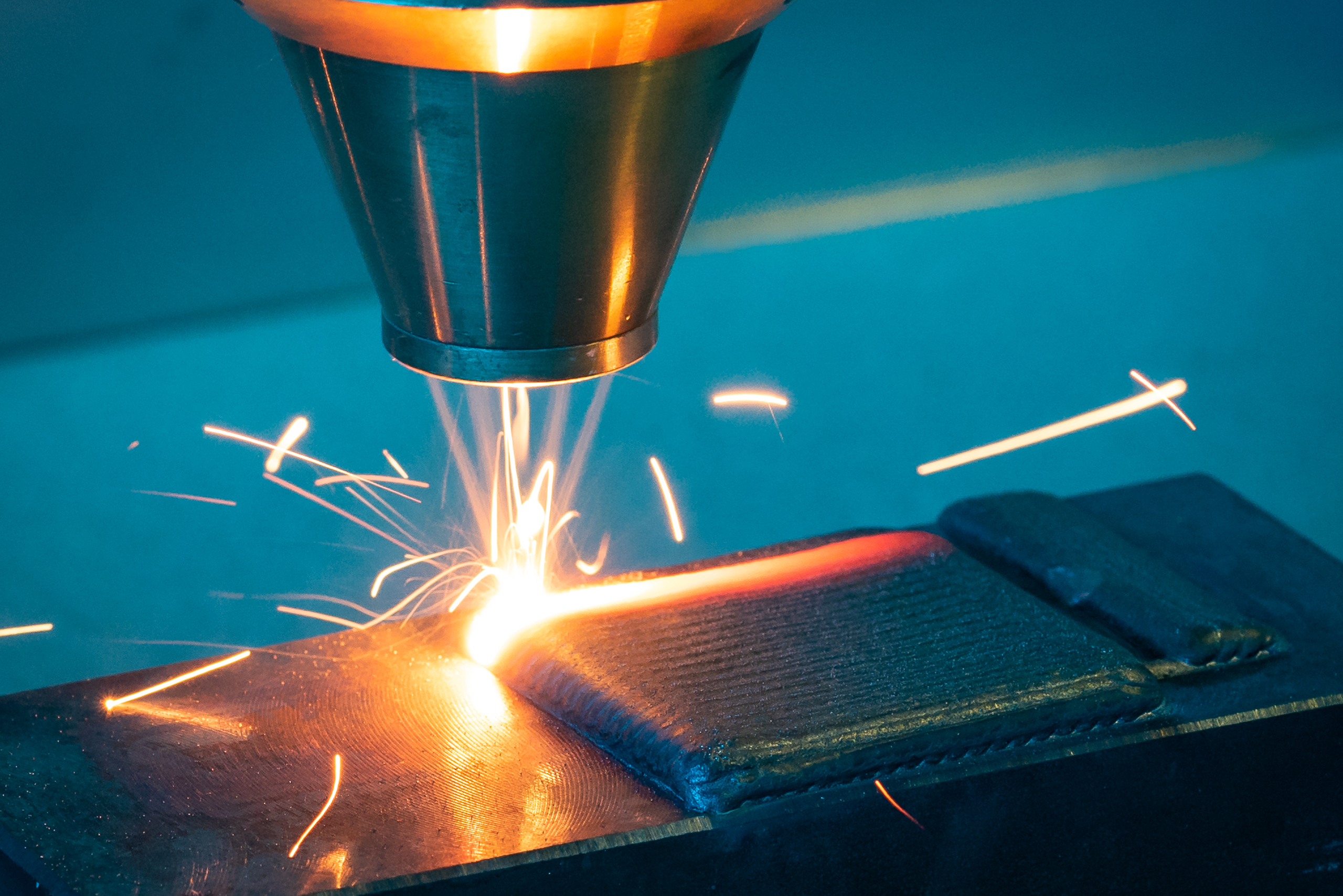
Figure 16: Laser cladding
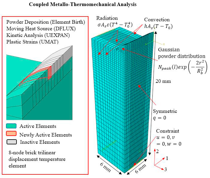
Figure 17: Boundary conditions and computational domains of the
coupled metallo-thermomechanical analysis [Ref]
Additive manufacturing (3D printing)
The 3D printing process uses a high-power laser to melt compositions of metallic feedstock from a powder bed.
In 2018, the Department of Mechanical Engineering University of Sheffield published an article that developed a model to assess residual stresses in selective laser-melted Ti6Al4V. The investigators simulated the model with the ABAQUS software and the DFLUX subroutine. They used the subroutine to write a moving volumetric heat source program to simulate the laser. An Abaqus user subroutine example like this is one of the most important areas of research nowadays.
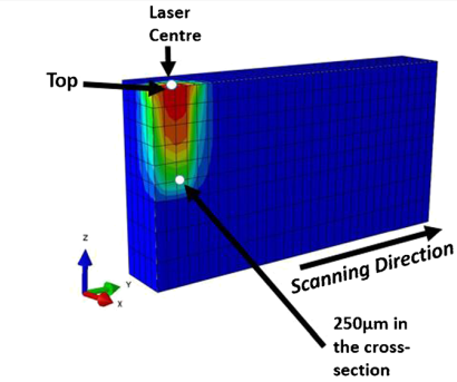
Figure 18: Location for temperature estimation [Ref]
Friction stir welding
In 2019, Pandit Deendayal Petroleum University of India developed a 3D finite element model with the ABAQUS subroutine to predict the thermal gradient of cooling-assisted friction stir welding. The generated heat during friction stir welding was applied as the surface flux over time. This was done by the DFLUX subroutine.
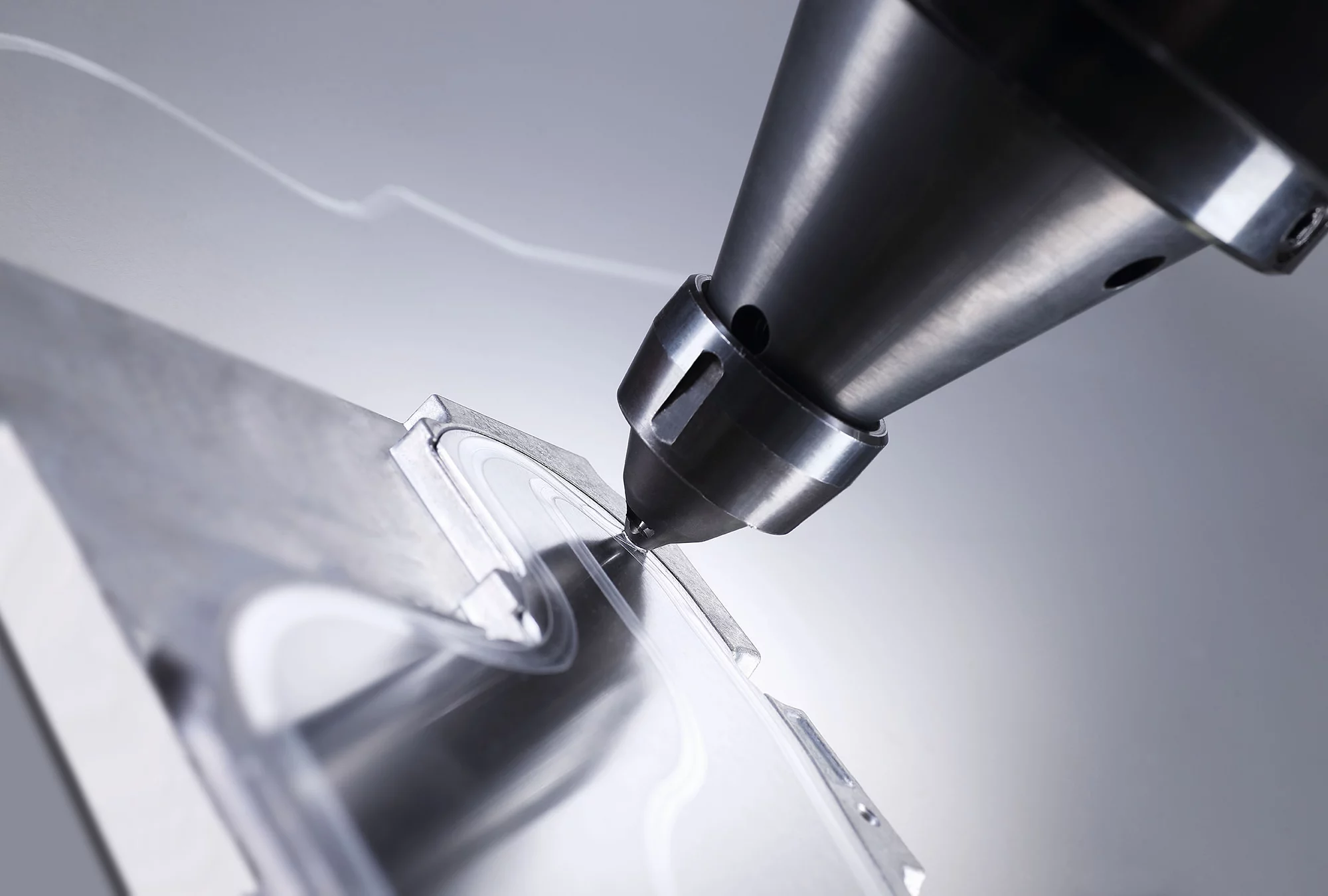
Figure 19: Friction stir welding
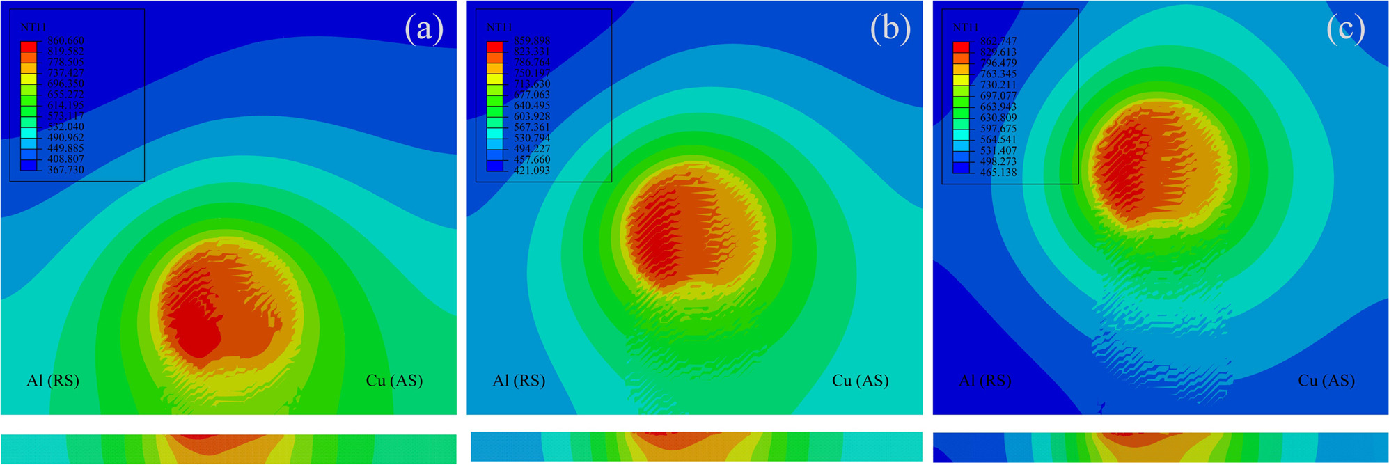
Figure 20: Thermal profile during weld stage [Ref]
Note: Tutorial and more examples of this fascinating subroutine:
Now, get the free example of the DFLUX subroutine in the following.
5. DISP & VDISP subroutine
The last ABAQUS subroutines that we are going to explain are DISP and VDISP. These are for specifying prescribed boundary conditions. The DISP is used in the ABAQUS/Standard solver, while the VDISP is used for the ABAQUS/Explicit solver. When you need to define time-dependent and location-dependent boundary conditions simultaneously, while the ABAQUS features cannot support these problems, the DISP and VDISP subroutines will come to your aid.
DISP and VDISP applications
Groundwater
In 2018, China Postdoctoral Science Foundation funded an article that simulated a finite element model by the ABAQUS and DISP subroutine to investigate the groundwater level fluctuation over time.
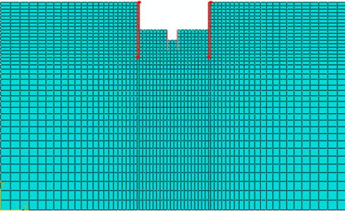
Figure 21: Calculation model [Ref]
Soft tissue
In 2016, the Department of Mechanical Engineering of Sharif University developed a constitutive and micromechanics modeling of connective soft Tissues. The researchers simulated the model with the ABAQUS subroutines such as UMAT and DISP. They used the DISP subroutine to model the periodic boundary conditions.
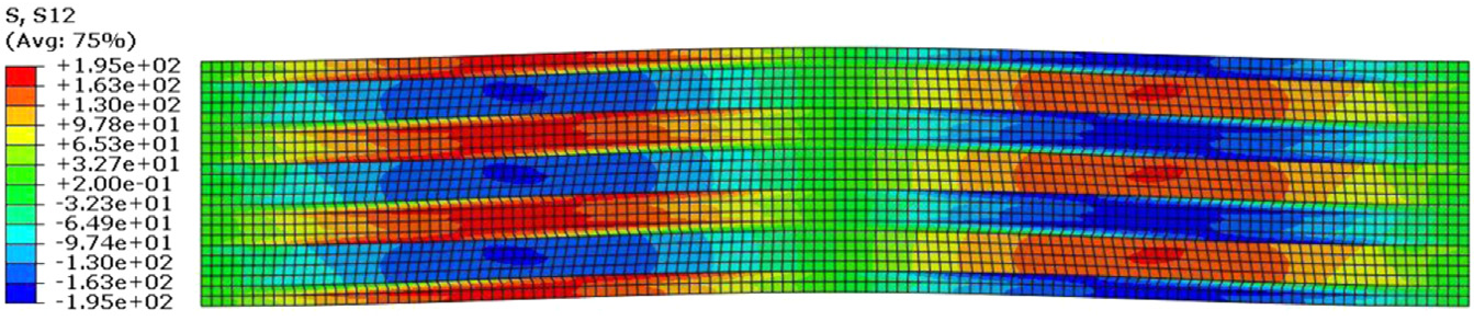
Figure 22: Shear stress distribution of rat tail tendon [Ref]
Sheet metal forming
In 2021, Shenzhen Key Laboratory of Cross-scale Manufacturing Mechanics investigated on sheet metal forming assisted by Ultrasonic vibration. The investigators simulated an analysis with the ABAQUS subroutines such as VUMAT and VDISP. The VDISP subroutine established the forming tool’s predefined path.
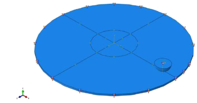
Figure 23: Boundary conditions and predefined forming tool path [Ref]
Get this post as a PDF file: caeassistant.com 10-useful-abaqus-subroutinepart2
Citations:
[1] https://www.industryarc.com/Research/Finite-Element-Analysis-Market-Research-502582
[2] https://www.transparencymarketresearch.com/finite-element-analysis-analysis-software-market.html
[3] https://www.lxsim.com/en/blog/what-are-the-main-applications-of-finite-element-analysis-fea/
[4] https://www.stymertech.com/blog/why-fea-is-important-in-industry/
[5] http://www.designtechsys.com/articles/fea-services[/vc_column_text]


One Response
This article was great. I read part 1 of this article and I was eager to read part 2. Now, in your opinion, which educational package should I buy to start learning?