Have you ever wondered why a quartz crystal can generate electricity just by being pressed? This isn’t magic—it’s the piezoelectric effect, a real physical phenomenon found in specific materials that convert mechanical stress into electrical energy and vice versa.
These materials aren’t just theoretical curiosities. They’re widely used in everyday technologies, from medical ultrasound devices and aircraft sensors to energy-harvesting systems in civil structures. Understanding how piezoelectricity works—especially the role of dipole alignment and the importance of material symmetry—is key to making the most of their capabilities.
In this blog, we explore the science behind piezoelectric materials and show how to simulate their behavior using Abaqus. We’ll cover everything from the physical principles and material types to step-by-step instructions for modeling and analysis. Whether you’re an engineer or researcher, this guide is designed to help you apply piezoelectric analysis in real-world scenarios.
Introduction to Piezoelectricity | Piezoelectric Definition
Piezoelectricity refers to the ability of certain materials to generate an electric charge in response to applied mechanical stress—and conversely, to deform mechanically when subjected to an electric field. This unique interaction between mechanical and electrical domains has enabled a vast range of innovations in science and engineering.
Figure 1: Generate an electric charge in piezoelectric material
History and Discovery
The piezoelectric effect was first discovered in 1880 by Jacques and Pierre Curie. They observed that applying pressure to certain crystals, like quartz, induced an electric potential. This discovery laid the groundwork for modern piezoelectric sensors, actuators, and energy harvesting systems.
How Does Piezoelectricity Work?
In its unaltered state, a piezoelectric material contains electric dipoles or small electric charges that are dispersed randomly. Due to their varied orientations, these dipoles negate each other, resulting in no overall electric charge. However, when a DC electric field is applied (a process known as poling), it compels these dipoles to align in a uniform direction. This alignment leads to a net electric charge within the material.
The fascinating aspect is that even after the removal of the electric field, the dipoles do not entirely revert to their original random orientations. A portion of them remains aligned, which is referred to as remanent polarization. This characteristic enables piezoelectric materials to generate electricity when subjected to mechanical stress, even in the absence of an external electric field.
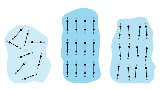
Figure 2: Dipole’s orientation [Ref]
In summary:
- Before poling: Dipoles are randomly oriented.
- During poling: The DC electric field aligns the dipoles.
- After poling: Some dipoles remain aligned, resulting in remanent polarization. This phenomenon is fundamental to piezoelectricity, allowing materials to produce electricity under stress.
Now the question arises: whether poling is necessary for a material to exhibit piezoelectric behavior.
Poling is necessary for polycrystalline piezoelectric ceramics (e.g., PZT) to exhibit piezoelectric properties, whereas single-crystal materials like quartz naturally possess aligned dipoles and do not require poling. Therefore, synthetic piezoelectric materials (such as ceramics and polymers) usually need to undergo a process called polarization to induce piezoelectric behavior. Natural piezoelectric materials like quartz do not require polarization.
The Piezoelectric Effect
Piezoelectric materials show two main effects:
The Direct Piezoelectric Effect occurs when mechanical stress is applied, resulting in the generation of an electrical charge, while the Converse Piezoelectric Effect occurs when the application of an electric field causes the material to undergo a physical change in shape.
- Direct Effect: Mechanical stress → Electric charge. This effect is commonly exploited in sensors and energy harvesters.
- Inverse Effect: Electric field → Mechanical deformation. Utilized primarily in actuators and precision motion devices.
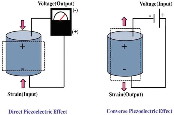
Figure 3: Piezoelectric effects [Ref]
Materials Exhibiting Piezoelectric Properties
Piezoelectric crystals can be natural or synthetic, with synthetics being divided into three categories: polymers, composites, and ceramics. Quartz, PZT, and PVDF are the well-known piezoelectric materials.
- Quartz: Natural crystal, stable and precise but with a weak piezoelectric response.
- PZT (Lead Zirconate Titanate): A widely used ceramic with a strong piezoelectric effect, ideal for sensors and actuators.
- PVDF (Polyvinylidene Fluoride): A flexible polymer used in biomedical and wearable devices.
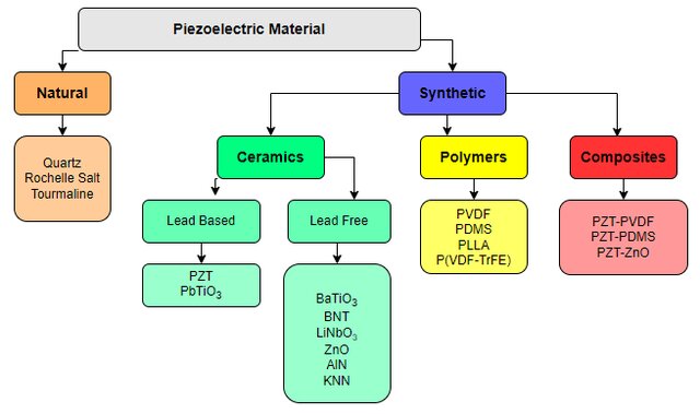
Figure 4: Piezoelectric material category [Ref]
Applications of Piezoelectric Materials in Industry
Piezoelectric materials are transforming industries due to their ability to convert energy between mechanical and electrical forms with high precision.
- Aerospace and Mechanical Engineering: Used in vibration control, structural health monitoring, and adaptive structures.
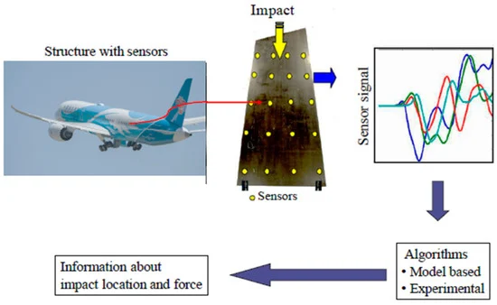
Figure 5: Impact monitoring of aircraft structures [Ref]
- Sensors and Actuators: Common in MEMS, robotics, automotive sensors, and haptic feedback devices.
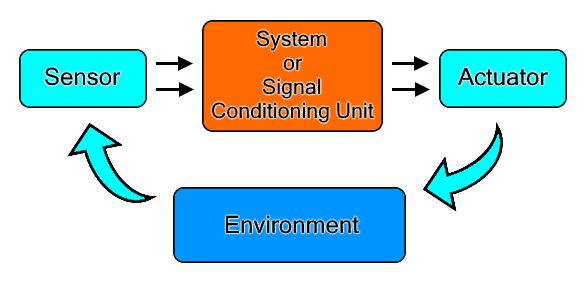
Figure 6: Sensor and actuator performance
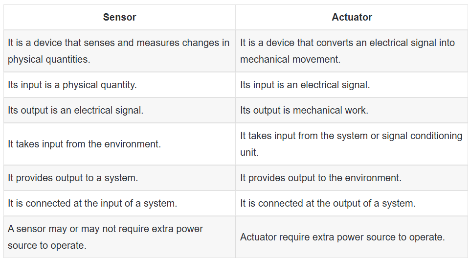
Figure 7: Sensor and actuator comparison
- Medical Devices: Integral in ultrasound transducers, hearing aids, and micro-pumps. In blood pressure measurement, piezoelectric sensors detect pressure changes in arteries, giving super accurate readings. They’re also used for pulse detection, where they keep track of your heartbeat and provide precise, real-time data on your pulse rate.
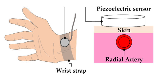
Figure 8: Piezoelectric sensor for pulse detection [Ref]
- Civil and Biomedical Engineering: Applied in smart structures, bio-sensing, and energy harvesting systems. Piezoelectric materials are a game changer for structural health monitoring in civil engineering. They’re used to keep an eye on things like bridges, buildings, and dams in real-time. These materials generate an electric charge when they’re stressed, making them perfect for detecting changes in structural integrity.

Figure 9: Structural Health Monitoring of Civil Engineering Structure [Ref]
Fundamental Theories and Formulas
Understanding piezoelectric behavior requires a foundation in material science and electromechanical coupling.
Crystallography and Symmetry
The piezoelectric effect originates from the crystallographic structure and symmetry of certain materials. Crystallography, the study of atomic arrangements in crystals, is key to understanding why only specific structures exhibit piezoelectric behavior. Crucially, a material must lack a center of symmetry for piezoelectricity to occur—this structural asymmetry allows an electric charge to develop when mechanical stress is applied, and vice versa.
The anisotropic nature of these non-centrosymmetric crystals means their piezoelectric response varies with direction, making symmetry analysis essential in predicting performance. For example, materials such as PbTiO₃ (Lead Titanate) and PZT (Lead Zirconate Titanate) contain atoms like lead (Pb), oxygen (O), titanium (Ti), and zirconium (Zr) arranged in a way that breaks inversion symmetry, enabling their piezoelectric properties.
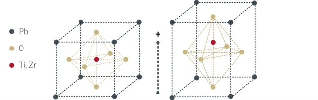
Figure 10: Crystallography and nonsymmetric of piezoelectric materials
The Curie point, often referred to as the Curie temperature, signifies the temperature at which a ferroelectric or piezoelectric material ceases to exhibit piezoelectric properties. Below a critical temperature known as the Curie point, materials possessing a perovskite crystal structure exhibit a dipole moment. For instance, in PZT (refer to Figure 10, right side), the material displays a minor dipole moment due to the off-centered position of the Zr4+ or Ti4+ cation. When the temperature exceeds the Curie point, the material adopts a simple cubic symmetry, resulting in the absence of a dipole moment (see Figure 10, left side).
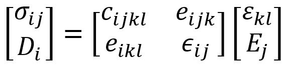
Basic Constitutive Equations
The electromechanical behavior of piezoelectric materials is described by a set of coupled constitutive equations. In matrix form, this coupling is expressed as:
Where:
 = stress tensor
 = electric displacement vector
 = elastic stiffness tensor
 = piezoelectric coupling tensor
 = strain tensor
 = electric field vector
 = dielectric permittivity tensor
- i,j,k,l=1,2,3, corresponding to the 3 spatial dimensions (x, y, z or 1, 2, 3).
This compact matrix representation highlights the intrinsic coupling between mechanical and electrical domains in piezoelectric materials. The behavior is governed by three fundamental tensors:
- Elastic Stiffness Tensor ():
Defines the relationship between stress and strain. It characterizes the material’s resistance to deformation and plays a vital role in determining its mechanical response under load.
- Piezoelectric Coupling Tensor ():
Describes how mechanical strain induces an electric field, and vice versa. It quantifies the electromechanical conversion efficiency of the material. - Dielectric Permittivity Tensor ():
Relates the electric field to electric displacement and characterizes the material’s ability to polarize in response to an electric field. Being a tensor, it accounts for directional dependencies in the material’s dielectric behavior.
Understanding and accurately modeling these constitutive relationships is essential for designing efficient piezoelectric devices, such as sensors, actuators, and energy harvesters.
For a detailed walkthrough, you can refer to our complete tutorial package available here.
Material Property Specification
The following material property specification outlines the key physical constants necessary for the modeling and simulation of piezoelectric behavior. These properties include:
- Elastic constants (e.g., Young’s modulus, Poisson’s ratio)
- Piezoelectric constants (e.g., the piezoelectric constants that describe the coupling between mechanical strain and electric field)
- Dielectric permittivity tensor (e.g., permittivity)
Step-by-Step Piezoelectric Simulation Materials in Abaqus
Piezoelectric simulation materials in Abaqus allows engineers and researchers to analyze the coupled electromechanical behavior of smart materials under various loading conditions. This section provides a step-by-step guide to setting up and running a piezoelectric simulation, from material definition to result interpretation.

Simulating piezoelectric behavior in Abaqus requires careful attention to the Multiphysics setup. Here’s a complete workflow:
1. Geometry Creation
Start by designing your model in Abaqus/CAE or importing it from a CAD tool. Geometry should align with real-world dimensions and be appropriate for electromechanical interaction.
2. Material Property Definition
Use Material > Create to input:
- Elastic properties (Young’s modulus, Poisson’s ratio)
- Piezoelectric matrix coefficients (d or e constants)
- Dielectric constants (relative permittivity)
In Abaqus, you’ll define the piezoelectric properties of your material in the material definition dialog. Here, you’ll input all the necessary values to describe the material’s mechanical and electrical behavior. These include: Elastic, Dielectric, and Piezoelectric Properties.
By setting these material coefficients up correctly, you’ll be able to simulate the behavior of piezoelectric materials accurately under different conditions!
Many common piezoelectric materials (especially ceramics like PZT) are treated as orthotropic for practical modeling, meaning they have three mutually perpendicular planes of symmetry with different properties along each axis.
Make sure to properly define the material orientation so that it aligns with the crystal axes, especially for orthotropic materials, as the piezoelectric response is highly direction-dependent.
Use Material > Create > Mechanical > Elasticity > Elastic > Type: Engineering constant to input engineering constant for (![]() ).
).
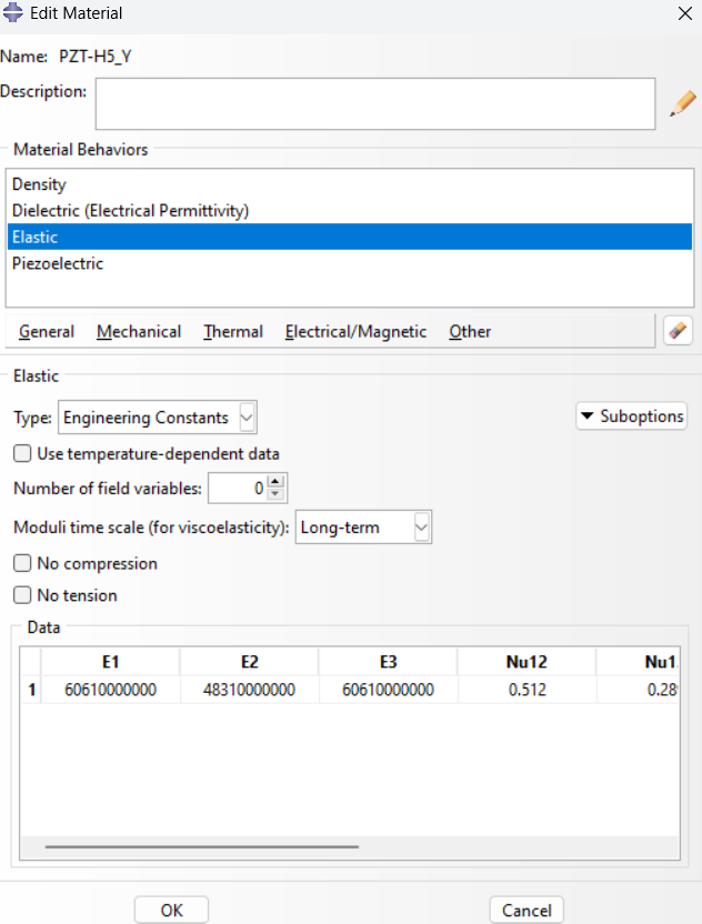
Figure 11: Defining Elastic Properties
Use Material > Create > Electrical > Piezoelectric > Type: strain to input piezoelectric coupling matrix (Strain Coefficients), (![]() ).
).
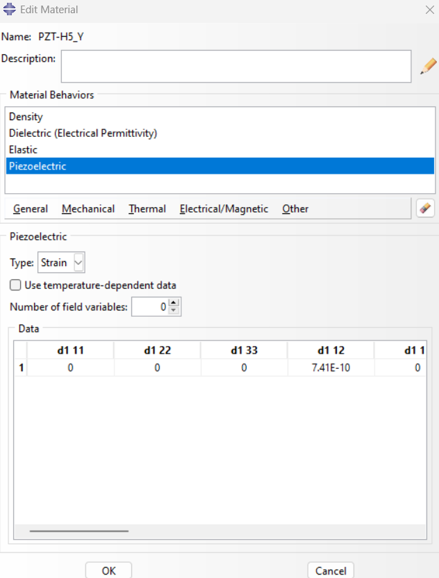
Figure 12: Defining Piezoelectric properties
Use Material > Create > Electrical > Dielectric > Type: Orthotropic to input dielectric matrix coefficients, (![]() ).
).
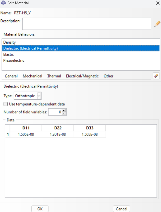
Figure 13: Defining dielectric properties
3. Meshing
Mesh Types and Element Selection
Use elements that support coupled-field analysis:
- For 2D: CPE4E (plane strain) or CPS4E (plane stress)
- For 3D: C3D8E
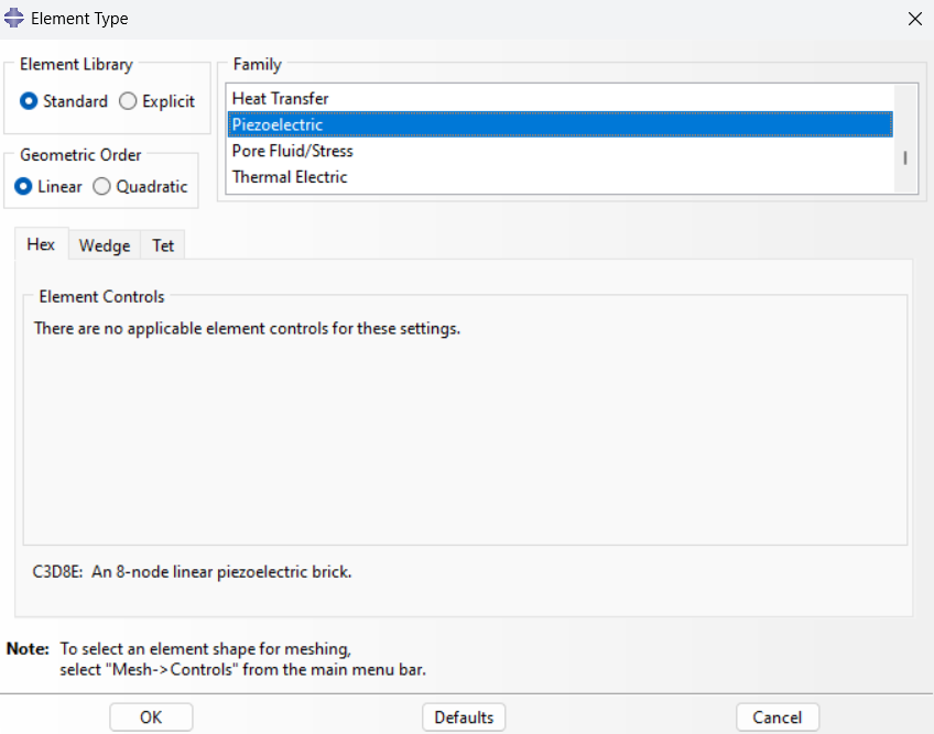
Figure 14: Choosing element type
Mesh Refinement
Adapt the mesh size to accurately capture regions with high-stress gradients or strong electrical field concentrations. Use local mesh refinement techniques, especially near edges, contact interfaces, and areas with abrupt geometric changes.
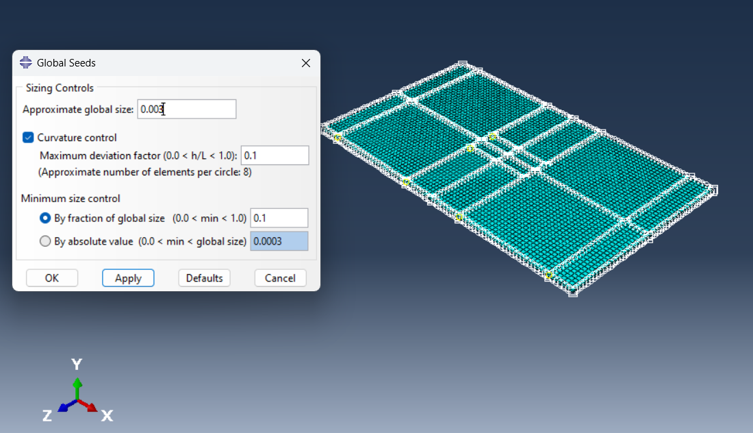
Figure 15: Meshing
4. Loading and Boundary Conditions
Applying Loads
- Mechanical: Forces, pressures, or displacements
- Electrical: Voltage or surface charge
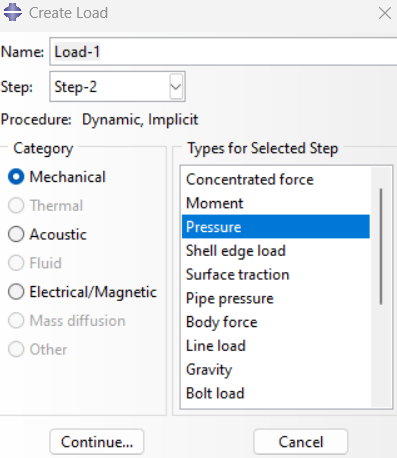
Figure 16: Loading
Boundary Conditions
Constrain displacement and electric potential appropriately. Ground one end to avoid floating nodes.
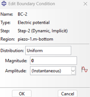
Figure 17: Boundary condition
5. Solving the Problem
Coupled Structural-Electrical Analysis
Use a static general step with fully coupled temperature-displacement-electrical fields.
Solver Settings
Ensure tight convergence criteria and enable nonlinear geometry (NLGEOM) if large deformations are expected.
5.6. Interactions
Ensure that the interactions between the mechanical and electrical components are established correctly.
The Tie constraint can be utilized in interaction modules to connect and bind or join two surfaces together.
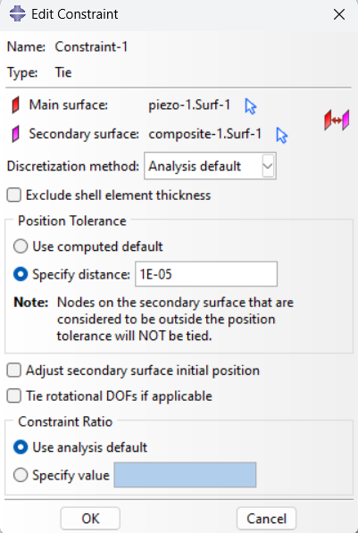
Figure 18: Interactions
The Tie constraint for linking two surfaces operates by scanning the area surrounding the master surface within a specified radius to locate the slave surface. Conversely, the equation constraint can be applied, such as in the case of electrical interactions. This constraint ensures that the piezoelectric surfaces maintain equal potential differences throughout the analysis.
By meticulously defining the coupled field analysis, selecting the appropriate solver and time-stepping methods, and accurately configuring the interactions, you will be able to effectively simulate piezoelectric materials in Abaqus.
7. Results
Plot:
- Displacement and strain fields
- Electric potential distribution
- Stress and electric flux density
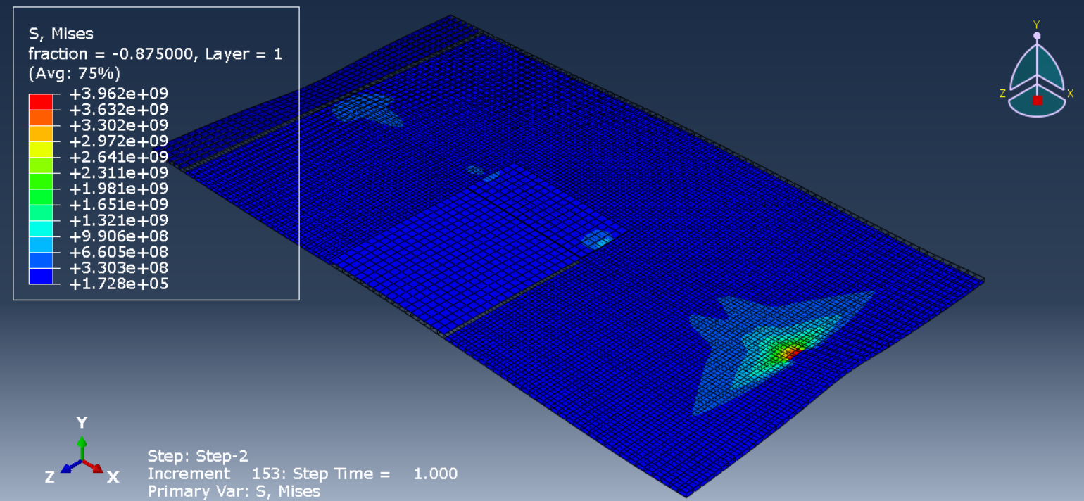
Figure 19: Results
It would be beneficial to consult the Abaqus documentation and tutorials to comprehend the challenges of initiating an Abaqus simulation. Furthermore, if you require information regarding the piezoelectric simulation in Abaqus, you can use this tutorial package:
Conclusion
This comprehensive guide provides an in-depth exploration of piezoelectric materials and their simulation using Abaqus. Starting with the foundational principles of piezoelectricity, the document explains the origin, underlying physics, and dual nature of the piezoelectric effect—direct and converse. The types of piezoelectric materials are outlined. A broad range of industrial applications is reviewed, covering aerospace, medical devices, civil infrastructure, and smart sensors, emphasizing the transformative impact of piezoelectric technologies.
The section on theoretical foundations delves into crystallography, symmetry, and the constitutive equations that govern electromechanical coupling, supported by a clear explanation of how elastic, piezoelectric, and dielectric matrices interact.
A detailed, step-by-step guide on modeling piezoelectric materials in Abaqus follows, providing instructions on geometry creation, material property input, meshing strategies, boundary condition setup, solver configuration, and postprocessing.
[/vc_column_text]
The CAE Assistant is committed to addressing all your CAE needs, and your feedback greatly assists us in achieving this goal. If you have any questions or encounter complications, please feel free to share it with us through our social media accounts including WhatsApp.
Explore our comprehensive Abaqus tutorial page, featuring free PDF guides and detailed videos for all skill levels. Discover both free and premium packages, along with essential information to master Abaqus efficiently. Start your journey with our Abaqus tutorial now!