
The cost of failed prints!! Did you ever think about that?🤔🤔Time and money wasted! just look at the pictures below: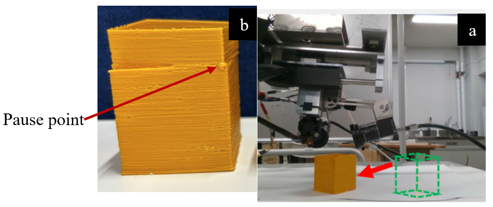
(a)moving printer piece (b) restart after pausing the printer [Ref]

Warped region [Ref]
Imagine spending countless hours designing a critical component, only to find a severely warped or cracked part. This common scenario results in massive waste of materials, resources, and time.
Studies show simulation can cut costs for low-volume parts by 50% to 75%.
Think of Additive Manufacturing Simulation as your GPS navigation system for 3D printing. Without GPS, you might try several routes before finding the one that avoids traffic jams (distortion) and bridge closures (cracks), wasting fuel (material) and time.
Simulation provides the optimal route (print parameters and orientation) right away, ensuring your delivery (final part) is perfect.
In this blog, we’ll explore how simulations enhance 3D printing. You’ll learn about key challenges in simulating processes, the role of advanced tools like Finite Element Analysis (FEA), and practical applications of software like Abaqus, ANSYS, and Simufact. Whether you’re a manufacturer or an enthusiast, this guide will help you understand the critical role of simulations in achieving superior 3D-printed parts.
Related Packages
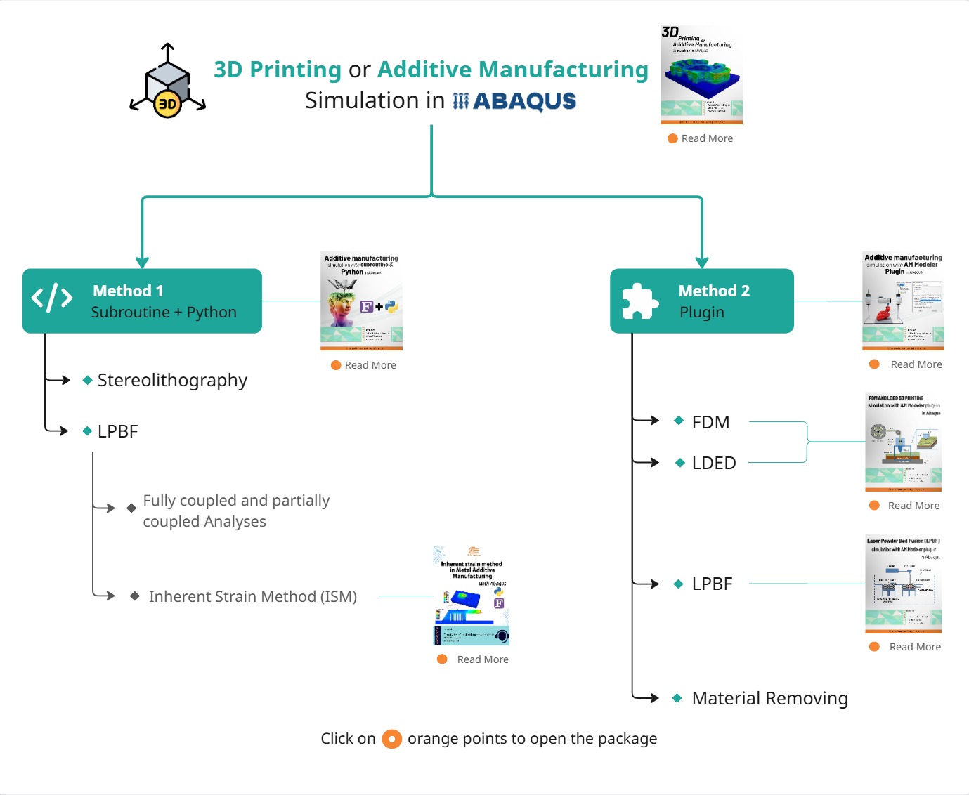
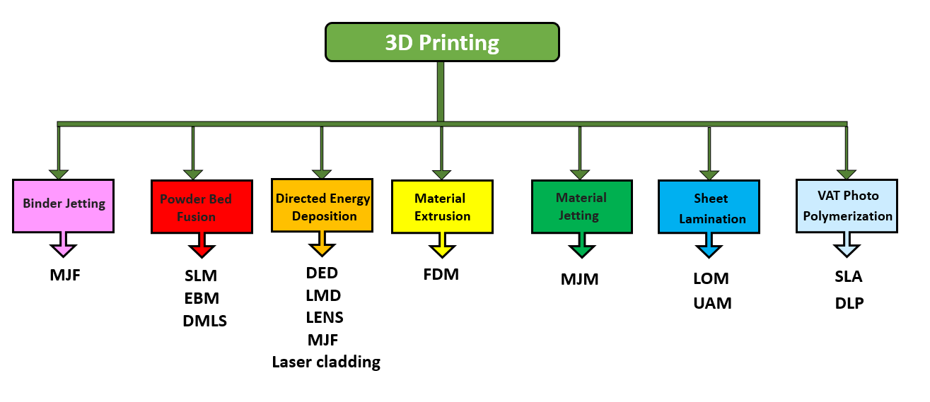
You may need a dedicated tutorial for your specific requirements. We offer a wide range of simulation tutorials covering various real-world problems. To explore our products and identify the most suitable package for your needs, please refer to the diagram below.
Please note that in Additive Manufacturing simulations, different methodologies may exist, but many of them share similar simulation procedures.
To make sure the selected package meets your expectations, feel free to speak with our experts via the website’s online chat. Our engineers will help you find the most appropriate package for your needs.
Why Additive Manufacturing Simulation is Critical?
Simulation is the crucial step that transforms Additive Manufacturing (AM) from an advanced capability into a reliable, full-scale production method. It models how materials behave under heat and stress, allowing engineers to predict and prevent potential issues such as thermal stress, warping, and material inconsistencies.
The rapid and localized thermal changes—required to melt and solidify material layer-by-layer—generate severe, unwanted defects:
Key Benefits of Integrating AM Simulation
Key Challenges in 3D printing Simulation
3D printing simulation faces key challenges that impact its accuracy and reliability. These issues arise from the complexity of the printing process, material diversity, and dynamic conditions during production.
- Multi-Physics Complexity
One major challenge is the multi-physics nature of the process, requiring precise inputs like thermal properties, material behavior, and particle geometry. Rapid temperature changes during printing can cause defects such as warping, cracking, or residual stresses, making accurate predictions difficult.
For example, Figure 3 highlights areas of high thermal stress (red zones) caused by uneven cooling during printing. These stress zones are critical in understanding potential defects in the final product.
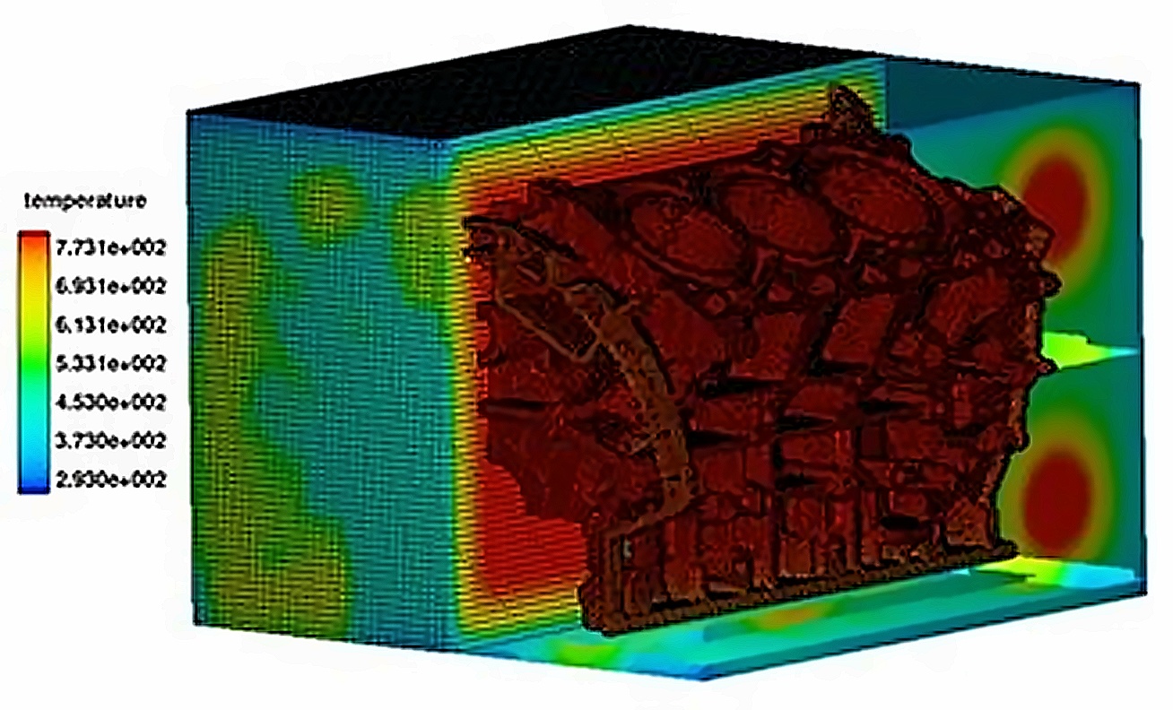
Figure 3: thermal stress analysis highlights areas of high stress (red zones) caused by uneven cooling [Ref]
- Geometric Complexity
Another challenge lies in the geometric intricacy of 3D-printed designs. Intricate shapes, overhangs, and lattice structures demand advanced algorithms to simulate stress points and deformations effectively.
As shown in Figure 4, a lattice structure requires highly detailed simulation to predict its performance under load. Such structures, while lightweight and efficient, often pose difficulties in ensuring reliability.
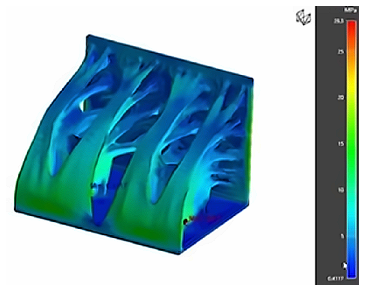
Figure 4: The geometric complexity of a lattice structure requires detailed simulation to predict its performance under load [Ref]
- Material Variability
Material variability adds further complexity. Metals may develop residual stresses due to uneven cooling, while plastics are prone to warping. Obtaining accurate material data for simulations remains a significant obstacle to achieving reliable results.
In Figure 5, a simulation of layer bonding and cooling in polymer 3D printing simulation demonstrates how materials react differently to thermal changes, highlighting the importance of accurate material modeling.
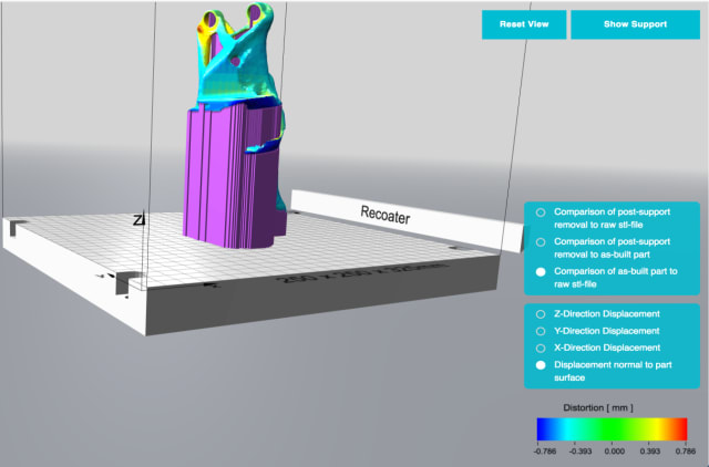
Figure 5: simulation of layer bonding and cooling in polymer 3D printing [Ref]
- High Computational Demands
Simulating 3D printing processes involves significant computational power. These simulations aim to replicate real-world conditions by modeling thermal behaviors, structural stability, and material interactions. For instance, in the case of printing a complex metal component like a turbine blade, the simulation must account for:
- Heat transfer between layers.
- Stress distribution to prevent cracking.
- Material shrinkage during cooling.
These intricate calculations often require substantial computational resources, making high-fidelity simulations costly and time-consuming. Figure 6 illustrates a thermal and stress simulation during layer loading, showing the insights achievable with adequate resources.
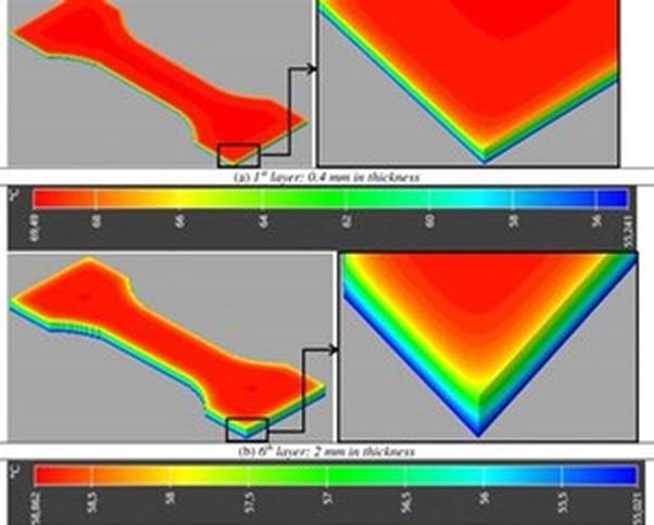
Figure 6: Thermal and stress simulation during layer loading [Ref]
Addressing these challenges requires advanced techniques, and this is where Finite Element Analysis (FEA) becomes crucial. FEA enables detailed modeling of thermal, structural, and material interactions, helping to predict and solve complex issues like warping and residual stress.
By dividing a complex object into more minor, manageable elements, FEA provides precise insights into how each part of a 3D-printed object behaves under specific conditions. This method enhances simulation accuracy and bridges the gap between theoretical modeling and real-world outcomes.
Industrial Applications and Case Studies
Additive Manufacturing (AM) is now a full-scale production solution for industries focused on bespoke or short-production runs, where significant lead time reduction and improved performance are key advantages.
| INDUSTRY | APPLICATION & GOAL | SIMULATION TOOL/BENEFIT |
|---|---|---|
| Automotive | Ford Motor Company used AM solutions to design vehicle brackets with better mechanical behavior and more effective heat dissipation via internal cooling channels. | Altair Inspire™ 3D printing simulation and HyperStudy® were used to identify error states (like support detachment) and optimize process parameters (e.g., Laser Power, Layer Thickness). |
| Aerospace & Defense | AM provides a competitive alternative for low volume, high cost parts. | Kongsberg Defense and Aerospace (KDA) utilized Altair to revolutionize satellite antenna designs, achieving lighter and more accurate outcomes. A military bracket was redesigned for metal 3D printing, resulting in a part 11 pounds lighter and $4,000 cheaper to produce. |
| Healthcare & Life Sciences | AM enables the development of individualized parts in a short timeframe, such as orthotics, orthopedic implants, and dental restorations. | Simufact supported research to develop procedures for the analysis of hybrid additive manufacturing for near-to-patient knee implants. |
| Tooling & Manufacturing | AM for tooling can reduce typical lead times from six months to six weeks. | Simulation optimizes cooling loops in injection molding to minimize part distortion. It allows for the full understanding of manufacturing requirements early in the process. |
The AM Simulation Workflow: How Do I Start AM Simulation?
The simulation process is essential for driving designs and influencing design directions, eliminating inefficiencies in physical trial-and-error. The following steps provide an organized path for initiating AM simulation:
Step 1: Specify the AM Technology to Simulate
The choice of simulation tools and models hinges on the AM process selected, which is extremely diverse:
| AM Technology | Process Focus & Simulation Goals |
|---|---|
| Fused Filament Fabrication (FFF/FDM) | Simulates plastic extrusion, focusing on warping (distortion), toolpath, speed, and surface quality. |
| Selective Laser Melting / Powder Bed Fusion (SLM/PBF) | Involves metal powder + laser, focusing on residual stress, distortion, temperature, and microstructure. |
| SLS / SLA / Binder Jetting | Requires different specific modeling approaches and physics. |
Step 2: Choose the Appropriate Simulation Software
Your choice depends on your goal (industrial prediction vs. advanced research) and your team’s coding experience:
| Software Focus | Example Tools | Analyst Recommendation |
|---|---|---|
| Industrial / Ready-made | ANSYS Additive Suite, Netfabb Simulation, Simufact Additive | Easier start, simple environments, less manual modeling required. |
| High Fidelity / Research | ABAQUS + subroutines | Best option for scientific AM simulation, customized physics, and microstructural analysis. |
Step 3: Master the Foundational Process Physics
Successful AM analysts usually have backgrounds in CFD or FEM/Mechanics. Key physics concepts to master include:
- Heat Transfer(Transfer across the layers)
- Stress / Strain Modeling
- Thermo-Mechanical Coupling(How thermal changes cause mechanical deformation)
- Material properties dependent on temperature
- Laser / Nozzle Toolpath
Step 4: Start Practically with a Simple Example
The recommended best learning path is to start by running a simulation on a simple model, such as a 20mm cube. This involves defining parameters (material, speed, power, thickness), running a thermal simulation, and then a thermomechanical simulation to predict distortion. Ideally, results should be compared with an actual physical print.
Abaqus Additive Manufacturing Simulation Workflow
ABAQUS (SIMULIA) is one of the most powerful tools for deep and accurate AM simulation and is considered the heart of many professional and scientific simulations. Abaqus 3D printing is used for complex thermomechanical problems, particularly in metal printing (SLM/DED), where high temperatures cause significant residual stress.
Abaqus capabilities essential for AM simulation:
- Sequential Thermomechanical Analysis:Abaqus is used to perform this core analysis, where the thermal analysis must be done first, and its results (temperature history) are applied to the subsequent structural analysis.
- Element Activation/Death:This capability is the main key to simulation, allowing Abaqus to model the melting and solidification cycle layer by layer, calculating stress and distortion as each layer is activated (EALIVE).
- Predictive Analysis:With accurate mechanical models, Abaqus can predict distortion, where cracks might initiate, and final residual stresses.
Abaqus is a powerful simulation software, ideal for tackling complex thermomechanical problems involving phase changes and large deformations. Widely used in aerospace and automotive industries, it excels at high-fidelity modeling, combining heat flow with stress and strain analyses.
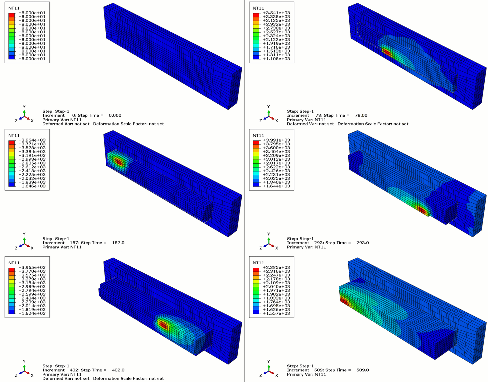
Figure 13: 3D printing simulation with Abaqus
The Abaqus 3D printing simulation is done via two methods:
- Using python scripting and subroutine: As previously mentioned, the model must first be sliced into layers. This can be done using CAD software, which is preferable, or directly within Abaqus. Each layer is printed (activated) during each step of the process. Additionally, when a layer is printed, its corresponding boundary conditions, material properties, and other factors must be applied according to the governing equations of the problem. These equations define variations in material properties, thermal conditions, and more. The tasks involved are handled through a combination of Python scripting and necessary subroutines. Once the inputs are provided, you simply run the Python code and wait for the analysis to finish.
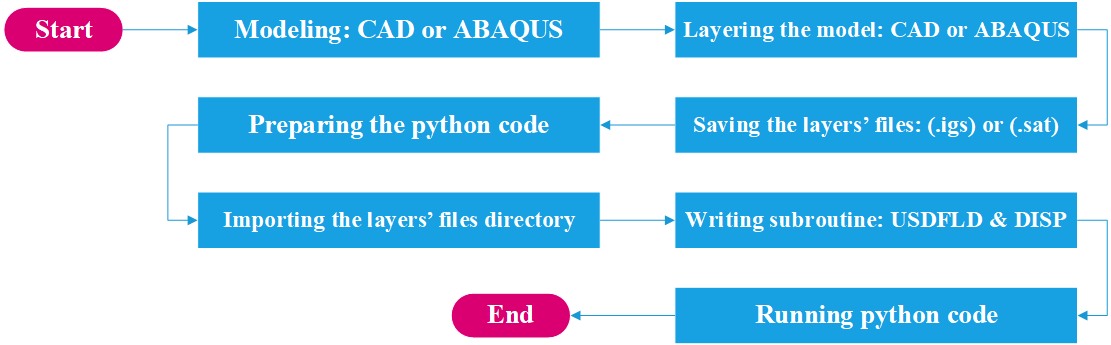
Figure 14: 3D printing simulation with python
2. Using AM Modeler plug in: The “AM Modeler” plug-in for additive manufacturing Abaqus simulation provides a user-friendly graphical interface that offers an efficient and scalable solution for simulating 3D printing, with minimal risk of errors. It eliminates the need for Python scripting, subroutine writing, or any other coding. All you need to do is input the necessary parameters, create a job, and start the simulation. This plug-in allows you to simulate popular 3D printing techniques such as Powder Bed Fusion (PBF), Direct Energy Deposition (DED), and Material Extrusion (ME).
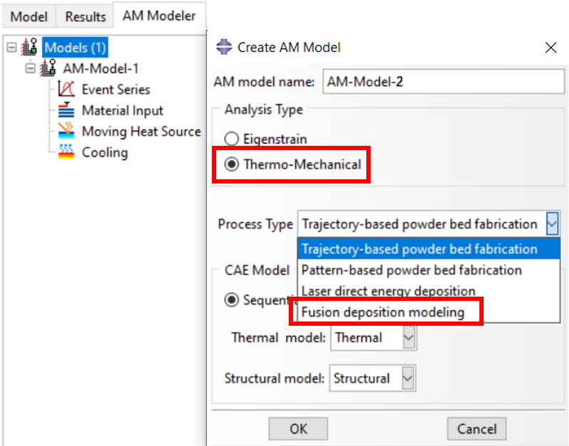
Figure 13 simulation is an example of FDM simulation using Abaqus with AM Modeler plug in. You can see below that there is an option specified for Fused Deposition Modeling (FDM) Process. You can learn all about it in the FDM Simulation in Abaqus tutorial.
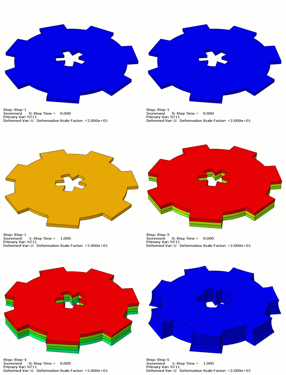
This is a stereolithography (SLA) 3d printing simulation using Abaqus with python scripting and subroutines. This is just 5 layers and the way to do this is shown in the flowchart on the left. You can learn all of these steps in our 3D printing simulation python scripting tutorial.
Discover the Inherent Strain Method in metal 3D printing (LPBF) with this step-by-step tutorial. Learn the theory and apply it with a practical Abaqus simulation using Python scripting and subroutines. All in our Inherent strain method in Metal Additive Manufacturing simulation tutorial.
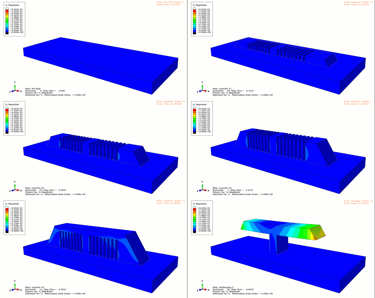
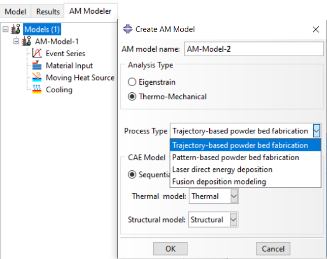
Figure 15: Abaqus AM Modeler plugin
What are the Key Important parameters in 3D Printing Simulation
Once the software is selected, the analyst must tackle the multi-physics complexity by defining precise inputs and applying governing equations to predict part performance and quality.
Key Input Parameters for Simulation Setup
To successfully run an AM simulation (which typically uses a Sequential Thermomechanical Analysis), the analyst must define inputs related to the build, the machine, and the material:
| Input Category | Required Parameters / Variables |
|---|---|
| Machine Inputs (Process) |
Speed of scan (or toolpath speed), Laser power (or nozzle temperature), Layer thickness, Hatch spacing. |
| Material Inputs |
Density (\( \rho \)), Specific Heat Capacity (\( C \)), Thermal Conductivity (\( k \)), Elastic Modulus, Poisson’s Ratio. Thermal properties must be defined as temperature-dependent functions. |
| Build Setup | Part orientation, support structure design, and the sliced model (layers). |
Thermal Analysis: Governing Equations and Parameters
Thermal analysis is crucial because rapid temperature changes cause defects like warping.
- Transient Heat Conduction:The primary mode of heat transfer is governed by the transient heat conduction equation:
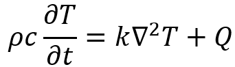
Here:
- ρ: material density,
- c: specific heat capacity,
- k: thermal conductivity,
- T: temperature,
- Q: internal heat generation,
- t: time.
This equation describes how temperature evolves over time and space. A specific case of this is Fourier’s Law, which relates heat flux to the temperature gradient:
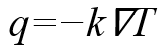
where q represents the heat flux vector.
- Heat Source Modeling:In laser-based printing, simple heat sources are insufficient. Models like the Goldak heat source (ellipsoidal model) are used in FEA software like Abaqus to provide a more realistic prediction of temperature distribution in the melt zone.
- Latent Heat:For melting and solidification, the latent heat of fusion (L) is accounted for, modifying the effective heat capacity to accurately predict phase change.
Mechanical Analysis: Stress, Strain, and Anisotropy
- Anisotropic Hooke’s Law (3D): The stress () and strain () relationship is defined using the stiffness matrix , which captures directional differences in material properties based on the print orientation.

- Infill and Lattice Structures:When dealing with complex geometries, the effective modulus (Eeff )of a lattice or honeycomb pattern is calculated based on the volume fraction (
 ) of the solid material within the pattern.


Advanced Meshing Techniques
Advanced meshing is crucial for capturing the exact behavior of 3D-printed parts. Tools like ANSYS and Abaqus utilize adaptive meshing to automatically refine the mesh only in regions with large gradients in stress or temperature, balancing accuracy and computational efficiency. A mesh convergence study should always follow meshing to verify the solution’s accuracy.
Additive Manufacturing Simulation Tools and Resources (The Decision Matrix)
Choosing the right software requires balancing license cost, hardware requirements, and training time. This guide provides a detailed view of the leading platforms tailored to specific AM needs.
Overview of Leading AM Simulation Software
| Software Platform | Primary Focus | Key Capability / Methodologies |
|---|---|---|
| ABAQUS | High-Fidelity Physics & Research | Sequential Thermomechanical Analysis, Element Activation/Death, Custom physics modeling via Subroutines, AM Modeler Plug-in. |
| ANSYS | Industrial & Thermomechanical | Coupled heat flow with stress analysis, Element Birth and Death (EKILL/EALIVE), Sequential coupling. |
| Simufact Additive | Metal AM (L-PBF, MBJ) & Post-Processing | Simulates entire production chain (sintering, heat treatment, machining). Automatic distortion compensation. PDA for defect analysis. |
| Simcenter | Process Simulation & Compensation | Predicts distortions; calculated distortions are used to automatically morph the initial geometry into a pre-compensated shape. |
| Altair Inspire | Design, Optimization & DFAM | Topology Optimization, Meshless FEA, rapid manufacturability evaluation. Leverages AI capabilities for comprehensive design exploration. |
| FLOW-3D AM | Micro-Scale Melt Pool Dynamics | Focuses on where defects originate: the melt pool. Identifies parameters that prevent defects such as porosity, lack of fusion, and keyhole instabilities. |
Recommended Educational Resources
For those starting out, tutorials are readily available. It is suggested that if the goal is only “predicting print quality” for FDM, simple tools like Cura plugins may suffice; however, metal processes require FEM.
- Free Training:ANSYS Additive Tutorials, Autodesk Netfabb Simulation Training.
- Key Literature:Additive Manufacturing Technologies (Gibson, Rosen, Stucker).
- Abaqus-Specific Training:Tutorials exist for using the AM Modeler plug-in for LPBF and FDM simulation, or for the subroutine and Python scripting method for complex simulations of parts like a gear or shaft with non-uniform cross-section.
Modern Trends and Future Directions in AM Simulation
The field of AM simulation is rapidly advancing, leveraging computational power and data science to tackle challenges at the micro and macro scales:
AI-Powered Design and Optimization
Generative design, which creates complex, organic shapes, is leveraging the power of Artificial Intelligence (AI). Altair’s solutions utilize AI capabilities, such as data mining and predictive models, for comprehensive design exploration through Design of Experiments (DoE) tools, helping to develop validated, manufacturing-ready designs. This integration optimizes product performance and reduces design and manufacturing time and costs.
The Digital Thread and Collaborative Platforms
The industry is moving toward a Digital Thread, which connects design, simulation, and production across all disciplines.
- 3DEXPERIENCE Platform (SIMULIA):This platform ensures seamless data integration and collaboration, offering advanced roles for digital product development. It provides features for Virtual Printing to simulate build behavior, predict distortion and residual stress, and ensure the as-manufactured geometry matches the as-designed geometry through digital compensation.
- Cloud and HPC:Simulation platforms utilize High-Performance Computing (HPC) and cloud solutions to manage the intense computational demands of multi-physics and high-fidelity AM simulations.
Micro-Scale Simulation (Melt Pool Dynamics)
A significant trend is the focus on simulating phenomena at the melt pool level, where defects originate.
- FLOW-3D AM: This software focuses on the precise physics of material behavior during melting and solidification. It helps analysts identify parameters that prevent microscopic defects such as porosity, lack of fusion, balling up, and keyhole instabilities.
- Materials Engineering:This includes designing metal alloys for AM by analyzing micro-mechanics simulations to understand grain orientation and phase properties. Advanced thermal-mechanical simulations can predict microstructure properties, including melt pool, unfused powder, phase transformation, and grain morphology.
- Process Window Optimization:Optimization engines, such as those in FLOW-3D (x), are used to explore vast parameter spaces, finding combinations that enable faster production without compromising part quality.
You may need a dedicated tutorial for your specific requirements. We offer a wide range of simulation tutorials covering various real-world problems. To explore our products and identify the most suitable package for your needs, please refer to the diagram below.
Please note that in Additive Manufacturing simulations, different methodologies may exist, but many of them share similar simulation procedures.
To make sure the selected package meets your expectations, feel free to speak with our experts via the website’s online chat. Our engineers will help you find the most appropriate package for your needs.
Conclusion: What We Wanted to Say, What We Said, and What We Learned
In this article, we explored the core ideas behind additive manufacturing simulation and why it has become a key part of modern engineering workflows. We began by explaining how simulation helps engineers predict distortion, residual stresses, and other critical issues before printing. This simple step reduces cost, prevents waste, and speeds up development.
What We Wanted to Say
We wanted to show that 3D printing simulation is not only useful but essential for anyone working with complex or high-value parts. Simulation allows you to understand process behavior early. It also gives you the freedom to adjust laser power, scan strategy, or layer thickness before committing to physical printing.
Throughout the article, we focused on two important strategies used in additive manufacturing simulation software.
First, we discussed the fully coupled thermal-mechanical approach. It is accurate, yet slow and expensive.
Then, we introduced the Inherent Strain Method. This method simplifies the process while keeping strong predictive power. It extracts strain values from micro-scale simulations and applies them layer by layer in a macro-scale model. As a result, engineers gain reliable distortion and stress predictions with far less computational effort.
What We Learned
By the end, we learned that the Inherent Strain Method offers an effective balance between accuracy and speed. It enables engineers to simulate larger parts in a practical way. With tools like Abaqus and its AM plug-ins, the workflow becomes even smoother.
Most importantly, we discovered that additive manufacturing simulation can be both accessible and powerful when supported by the right methods and software tools.
Final Thoughts
As the field grows, simulation will play an even bigger role in optimizing material usage, improving surface quality, and ensuring part reliability. With the right additive manufacturing simulation software, you can move from guesswork to confident, data-driven design. And with efficient approaches like the Inherent Strain Method, high-fidelity prediction becomes easier, faster, and far more practical.
Resources
https://www.3ds.com/products/simulia/additive-manufacturing-simulation
https://altair.com/additive-manufacturing
https://hexagon.com/products/simufact-additive




 English
  Korean
  Chinese