Metal forming simulation is the computational process of replicating metal shaping operations using finite element analysis (FEA) tools.
Metal forming is one of the most widely used manufacturing processes to shape metals into functional parts. From automotive body panels to aerospace structural components, forming processes involve large plastic deformation of metals and require precise control to avoid defects such as thinning, wrinkling, or residual stresses that can affect performance.
With the advent of advanced simulation tools like Abaqus, engineers can now virtually recreate forming processes, predict outcomes, and optimize manufacturing parameters without expensive and time-consuming physical trials.
This blog explores how to model various types of metal forming accurately in Abaqus, focusing on sheet metal forming, cold forming, and laser forming. We’ll dive into the materials and properties needed, solver choices, common challenges, and resources to get started.
WordPress is an open-source content management system used to build websites.
Yes. Abaqus supports ductile damage models and user-defined failure criteria to predict crack initiation and propagation.
Not always. Standard material models and contact algorithms often suffice, but subroutines like DFLUX enable specialized features such as moving laser heat sources.
Shell elements are generally preferred for thin sheet metal due to computational efficiency and the ability to represent bending accurately.
What is Metal Forming Simulation?
Metal forming simulation is the computational process of replicating metal shaping operations using finite element analysis (FEA) tools. By inputting material properties, tooling geometry, contact conditions, and loading sequences, simulations predict how metals deform, where stresses concentrate, and how the final shape behaves after unloading.
Why is It Important?
Simulating forming processes helps engineers:
- Predict defects such as thinning or cracks.
- Optimize tool designs and process parameters.
- Evaluate springback and residual stresses.
- Reduce trial-and-error in the manufacturing process.
- Save time and reduce costs associated with physical prototyping.
Common Industries and Use Cases
Forming simulation is used in various processes applicable to industries such as Automotive, Automotive, Consumer Electronics, Heavy Machinery, Innovative Design Exploration, and Aerospace.

Figure 1: Forming simulation for modern manufacturing

Figure 2: Simulation chip forming process
What are the Types of Forming Simulation?
Different forming processes require specialized simulation approaches. The most common are Sheet Metal, Cold, Hot, and Laser Forming.
- Sheet Metal Forming
Sheet metal forming includes processes like deep drawing, stamping, bending, and stretch forming, where thin sheets are shaped by dies and punches.
- Challenges: Handling large plastic deformation, thinning, wrinkling, and springback.
- Modeling: Typically uses shell or membrane finite elements due to the thin geometry.
You can learn more stuff and get more practice in our tutorial for forming.
- Cold Forming
Cold forming processes plastically deform metals at or near room temperature without significant thermal input.
- Processes: Roll forming, press braking, extrusion.
- Focus: Predicting plastic deformation, residual stresses, and springback.
- Modeling: Often uses plane strain or solid elements for 2D/3D simulations.

Figure 3: Simulation of cold forming
Get the full detail of the cold forming simulation in our Full tutorial.
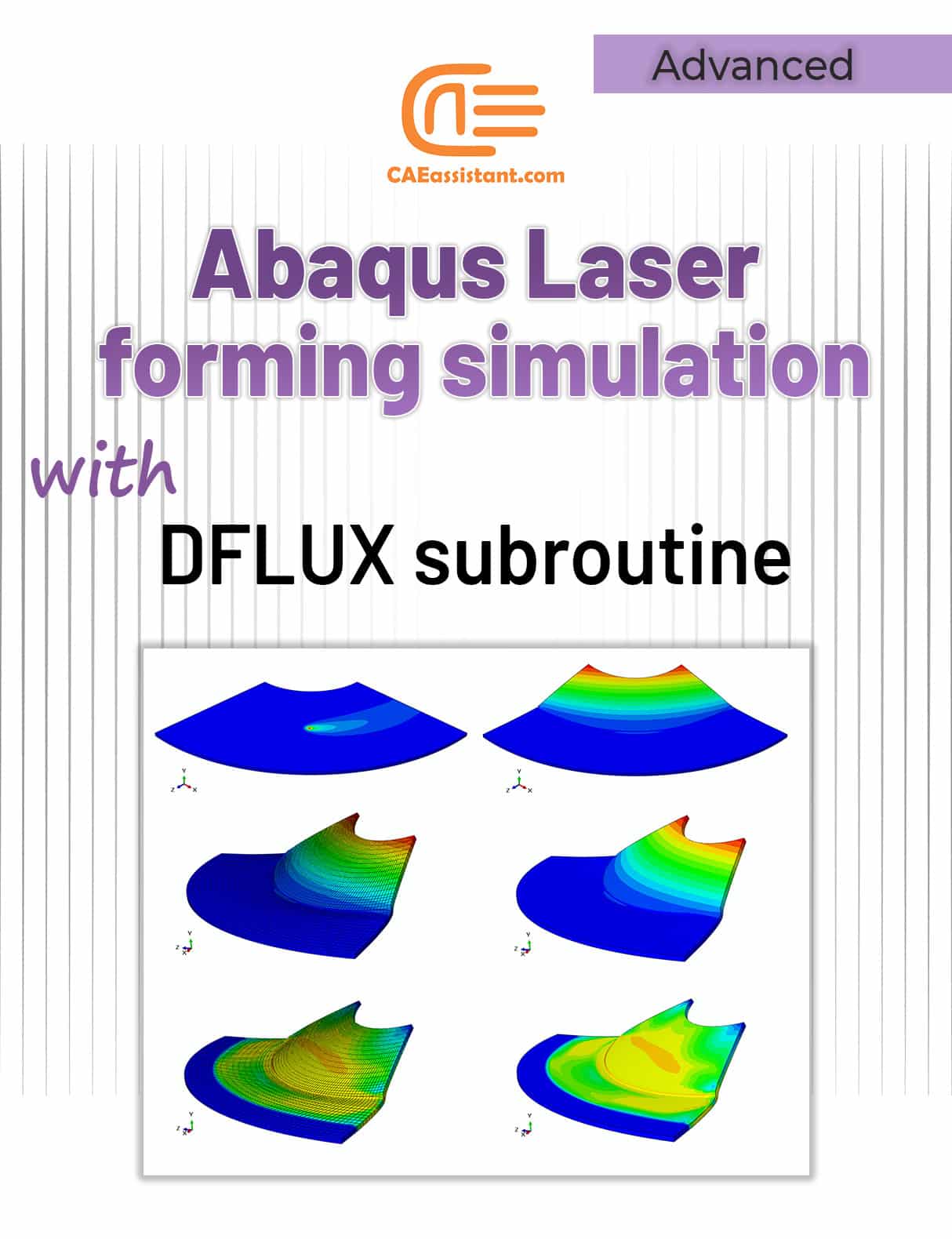
- Laser Forming
Laser forming induces shape change by localized heating and thermal expansion using a laser beam.
- Benefits: Contactless bending, precise control.
- Simulation: Requires coupled thermal-mechanical analysis to model transient heating and stress evolution.
- Special Techniques: Use of user subroutines (DFLUX) to apply moving laser heat flux.

Figure 4: Laser Forming Process
Get the full detail of the laser forming simulation along with the subroutine file in our tutorial.
- Hot Forming and Advanced Techniques
Processes like hot stamping, superplastic forming, or incremental sheet forming involve elevated temperatures or novel mechanisms.
- Note: These require advanced material models and thermal coupling, typically covered in dedicated tutorials.
What Materials and Properties Work Best for Forming Simulations?
Accurate material data is critical for forming simulations. Metals undergo plastic deformation, strain hardening, and sometimes damage or failure during forming.
Plasticity Modeling
- Yield Criteria: Most forming metals follow the von Mises yield criterion.
- Hardening Models: Isotropic hardening (uniform strengthening) or kinematic hardening (Bauschinger effect).
- Strain Rate: Some metals show rate sensitivity; strain rate-dependent models improve accuracy.
Damage and Failure
- Ductile Damage Models: Capture initiation and evolution of cracks or necking.
- Fracture Criteria: Used to predict tearing or splitting in sheet metal.
Recommended Properties for Common Metals
- Steel: Flow curves, yield stress, tensile strength, strain hardening exponent.
- Aluminum: Lower strength, higher ductility — strain-rate effects important.
- Titanium: High strength-to-weight ratio, requires detailed plasticity models.
Material Data Sources
- Experimental tensile tests and hardness measurements.
- Literature and material databases.
- Manufacturer data sheets.
How to Simulate Sheet Metal Forming in Abaqus
Sheet metal forming simulation requires careful setup to ensure realistic results.
Geometry and Elements
- Use shell elements (S4R, S4) to represent thin sheet metals effectively.
- Define thickness accurately; shell elements inherently consider thickness.
Boundary Conditions
- Fix tool parts (dies, punches) using displacement or velocity boundary conditions.
- Model sheet metal as deformable with appropriate constraints for clamping.
Contact and Friction
- Define contact interactions between tools and sheet using Abaqus contact algorithms.
- Use realistic friction coefficients (e.g., Coulomb friction 0.1–0.3) to simulate metal-tool sliding.
Material Modeling
- Apply elastic-plastic constitutive laws with isotropic/kinematic hardening.
- Include strain-rate dependence if forming speed is high.
Common Challenges and Solutions
- Thinning: Monitor strain distribution; high thinning can lead to failure.
- Wrinkling: Model proper boundary constraints and compressive stresses.
- Springback: Use unloading steps to simulate elastic recovery; validate against experiments.
Abaqus Forming Simulation | Example: Deep Drawing Analysis
Simulate the deep drawing procedure for a cylindrical container by utilizing the geometric and mechanical specifications outlined in the figures and tables below; subsequently, calculate the force needed by the punch to accomplish this task. The punch descends into the sheet by 60 mm.

Figure 5: Deep drawing sketch
Step 1: Geometric Modeling (Part Module)
Each component is created within the Part module. Assign a name to each piece to enhance your accuracy and efficiency!
Sheet modeling
Access the Sketch environment through the following route:
Part→ Create→ Name: Blank; Axisymmetric; Deformable; Shell; Approximate size: 0.3
To model punch, follow the path:
Part→ Create→ Name: Punch; Axisymmetric; Analytical rigid; Wire; Approximate size: 0.2
Step 2: Establishing the Geometric and Mechanical Properties (Property module)
Create a new material using the create material tool, and enter Steel for the material name and 7800 for the density, Young’s modulus, and Poisson’s Ratio, which are 2e11 and 0.3, respectively. Then, in the same dialog box, choose the path.
Mechanical →Plasticity → Plastic
to describe the plastic properties using the figure below.

Figure 6: Defining material properties
Step 3: Assembly Module
In this module, we create instances of all the components in independent modes, such as sheet:
Instance → Create → Blank → Apply

Figure 7: Assembly Model
Step 4: Defining the Type of Solution (Step Module)
Only one step is required to analyze the deep drawing of the sheet using the Explicit method (I mention it because several steps are needed if you want to do it using the Implicit method). So, create a Step named ‘Deep Draw’ of Dynamic explicit type with ‘Time Period’ 0.007.
Step 5: Defining Contacts (Interaction Module)
First, define the mechanical properties of the contact surfaces in the Interaction module by defining two Interaction Properties; the first characteristic is the contact surface between sheet and punch, which is defined as friction-free (we call it Frictionless), and the second characteristic belongs to two surfaces: blank-holder with sheet and matrices with a sheet by the friction of 0.1.
The procedure is shown below:

Figure 8: Defining Contacts
In the second case, choose the Penalty option to define the friction and name it ‘Friction’.
Step 6: Applying Load (Module Load)
In the current analysis, the goal is to apply the punch movement and the blank holder force in the form of a smooth function to the path below and according to the figure. (Because we do not want the load to accelerate significantly and hence remain quasi-static)
Tools → Amplitude → Create → Name: Load Amplitude, Type: Smooth step → Continue.
Step 7: Meshing
We only need to mesh the sheet.

Figure 9: Meshing
Step 8: Problem-Solving (Job Module)
We proceed to the Job module to establish a new Job titled Deep in order to address the issue. Once you have resolved the problem, please click the Results button to view the outcomes.
Step 9: Examining the Results (Visualization Module)
Save the model and observe the desired results.

Figure 10: Deep Drawing Results
For detailed notes of the tutorial, you can download the full PDF and access the complete guide here:
Forming process simulation full Guide PDF
Which Abaqus Solver Should You Use for Forming Simulation?
When choosing between Abaqus/Standard and Abaqus/Explicit for forming simulations, the key is to match the solver’s strengths with the complexity of your process—start simple, and switch if needed.
Abaqus/Explicit
- Best for simulations with severe contact, complex nonlinearities, and large deformations.
- Suitable for highly dynamic forming operations or when the Standard solver fails to converge.
- Uses an explicit time integration scheme; computationally intensive but stable for complex contact.
Abaqus/Standard
- Suitable for quasi-static processes with smooth loading.
- Uses implicit time integration; faster convergence in many cases, but may struggle with severe contact or complex material behavior.
Tips for Solver Selection
- Start with the Standard solver for simple forming steps.
- Switch to Explicit if convergence issues arise or contact is highly nonlinear.
- Use mass scaling in Explicit to reduce computational time, but carefully monitor physical accuracy.
How Do You Ensure Accurate Results in Forming Simulations?
To ensure accurate results in forming simulations, focus on high-quality meshing, proper convergence control, careful use of mass scaling, and thorough post-processing validation.
Mesh Quality and Size
- Use a finer mesh in critical deformation zones.
- Balance mesh density with computational resources.
Controlling Convergence
- Monitor contact status and adjust penalty parameters.
- Use automatic stabilization if available.
Mass Scaling in Explicit
- Increase the stable time increment by adding artificial mass cautiously.
- Validate results against smaller timestep runs.
Post-Processing Checks
- Inspect the thickness distribution to identify thinning.
- Evaluate the springback angle and compare with experimental or analytical data.
- Analyze residual stress patterns.
Conclusion
In this blog, we explored how to accurately model sheet metal, cold, and laser forming simulations using Abaqus. By understanding the different types of forming processes, selecting appropriate material properties, and setting up the right solver and mesh configurations, you can effectively predict and address common challenges such as thinning, springback, and residual stresses.
Abaqus’s versatile tools—from explicit and standard solvers to thermal-mechanical coupling—make it possible to simulate complex forming operations with confidence. With the range of tutorials and simulation packages available, getting started and advancing your skills in forming simulations has never been easier. Whether for industry applications or research, Abaqus provides a robust platform to optimize forming processes and accelerate product development.
The CAE Assistant is committed to addressing all your CAE needs, and your feedback greatly assists us in achieving this goal. If you have any questions or encounter complications, please feel free to share it with us through our social media accounts including WhatsApp.
Explore our comprehensive Abaqus tutorial page, featuring free PDF guides and detailed videos for all skill levels. Discover both free and premium packages, along with essential information to master Abaqus efficiently. Start your journey with our Abaqus tutorial now!