Did you know that more than 50% of failures in composite structures come from incorrect design or simulation? Composites are everywhere—in aerospace, automotive, energy, and beyond. Their unique strength-to-weight ratio makes them powerful materials, but modeling and simulating them is never straightforward.
To run a successful composite simulation in software like Abaqus, you need more than just software skills. You must understand the fundamentals of composites, know how they behave differently from metals, and be familiar with concepts like anisotropy, multiscale modeling, and damage criteria. Without this foundation, your results may be misleading—or worse, completely wrong.
In this blog, we’ll give you a clear roadmap for composite analysis. We’ll start with the basics of what composites are, explore their different types, and explain why simulation matters. Then, we’ll dive into key concepts like multiscale modeling, failure criteria, damage, and fatigue. Finally, we’ll walk through a step-by-step guide for running a composite simulation in Abaqus, and share resources—including a free tutorial PDF—to help you practice and deepen your skills.
📝 For a complete step-by-step walkthrough with images, settings, and examples in Abaqus, download our FREE Composite Simulation Tutorial (PDF) here:
What are Composite Materials?
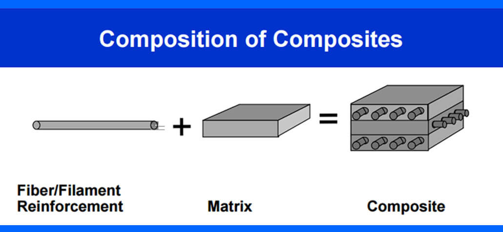
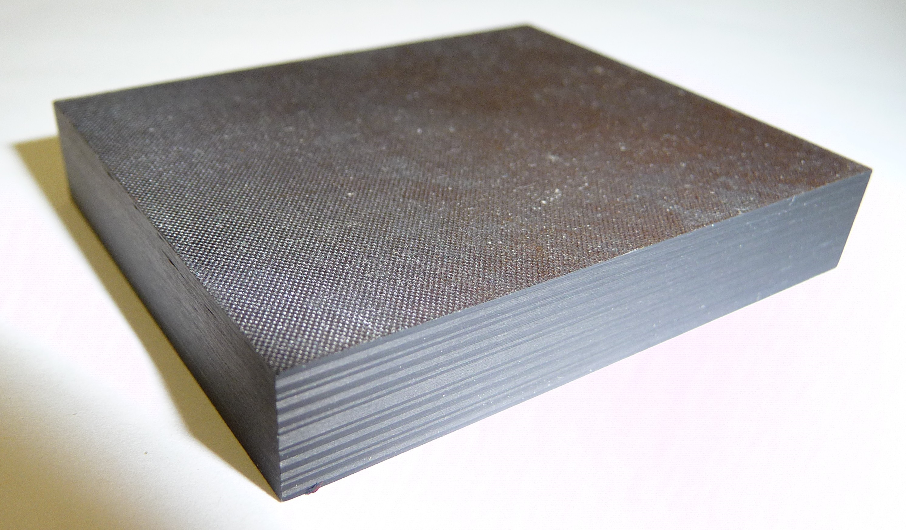
Composites are materials made by combining two or more different materials to get better properties than each one alone. They don’t fully mix like alloys. Instead, each part keeps its identity but contributes to the final strength and performance.
A composite usually has two main parts:
-
Matrix: the base material that holds everything together.
-
Reinforcement: the stronger material that improves stiffness, strength, or other properties.
This teamwork is why composites are popular in industries that demand lightweight but strong designs. If you’re working in composite analysis or planning to try composite simulation, understanding this basic structure is the first step.
Now that you know what composite material is, let’s talk about “why we need them?” What are the advantages and disadvantages of these materials?
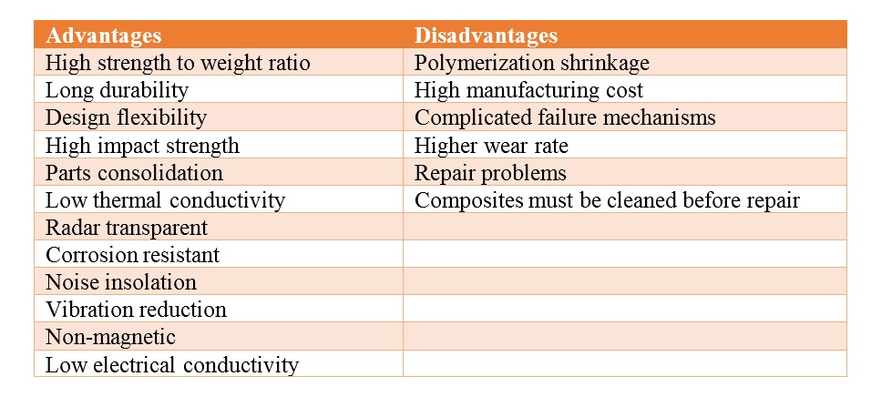
Advantages and Disadvantages of Composite Materials
Like every material, composites come with benefits and trade-offs.
Compared to other common materials, composites are known mostly because of their strength and lightness. Imagine you want to design a plane; you must select a material with properties such as high strength, being as light as possible to fly, and being flexible. Common materials like steel have the strength we need, but they’re heavy and do not have the flexibility we need. Well, the best choice would be composite.
Manufacturers can create qualities that precisely meet the needs of a specific structure for a specific purpose by selecting the right reinforcing and matrix material mix. Take a look at the table below; there are some advantages and disadvantages of these materials.
Examples of Composite Materials
You don’t have to look far to see composites in action.
Natural composites include:
-
Wood → fibers in a natural matrix.
-
Bone → mineral reinforcement in collagen.
-
Human hair → keratin structure giving strength and flexibility.
Engineered composites are everywhere:
-
Fiberglass (GFRP), Carbon Fiber (CFRP), Kevlar → aircraft, cars, protective gear.
-
Reinforced concrete → bridges and skyscrapers.
-
Translucent or absorbent concrete → modern architectural designs.
-
Consumer goods → bathtubs, countertops, boat hulls.
From airplanes to shower stalls, composites combine lightness and toughness in ways no single material can. That’s why engineers invest in composite simulation—it gives them confidence before manufacturing.
How Composites Behave Differently from Metals (anisotropy, heterogeneity, multiple failure modes)
Composites do not behave like metals. While metals are isotropic and show the same properties in all directions, composites are anisotropic—their strength and stiffness depend on the fiber orientation. This gives composites a much higher strength-to-weight and stiffness-to-weight ratio, which is ideal for lightweight structures.
However, this also brings differences in how they fail. Metals are ductile, meaning they can deform plastically and absorb energy before breaking. Engineers usually see warning signs, such as yielding, before final failure. Composites are more brittle and can fail suddenly through mechanisms like fiber breakage, matrix cracking, or delamination.
On the plus side, composites resist corrosion better than metals. But they are also more sensitive to impact damage and manufacturing defects. Metals, by comparison, are generally tougher, easier to repair, and more recyclable.
Anisotropy
Metals are usually isotropic, meaning their properties (strength, stiffness, expansion) are the same in all directions.
Composites are anisotropic, which means their properties vary with direction. For example, a unidirectional carbon fiber laminate is extremely stiff along the fiber axis but much weaker across it.
This is why fiber orientation and ply stacking are so critical in Abaqus composite simulations—a design is only as strong as the weakest direction.
Heterogeneity
Metals are uniform at the microscopic scale (a block of aluminum is aluminum everywhere).
Composites are heterogeneous, made of two or more different materials (matrix + reinforcement). Each component has unique properties, and together they create new behaviors.
This heterogeneity gives composites high strength-to-weight ratios, but it also makes their behavior harder to predict without advanced composite analysis tools.
Multiple Failure Modes
Metals usually fail in a relatively predictable way—through yielding and plastic deformation, followed by fracture.
Composites, on the other hand, can fail in several ways:
-
Fiber breakage.
-
Matrix cracking.
-
Fiber–matrix debonding.
-
Delamination between plies.
-
Progressive damage and fatigue over time.
These mechanisms can happen individually or simultaneously, and they often interact. That’s why simulation must include advanced failure criteria (Hashin, Puck, Tsai-Wu, etc.) to capture real-world behavior. Don’t worry we will explain this more in the next sections.
Design Implications
Because composites behave differently from metals, engineers can’t just “swap” steel for carbon fiber and expect the same results. Instead, the entire structure must be designed and analyzed with anisotropy and multiple failure modes in mind.
This is where composite simulation becomes crucial—it allows engineers to understand how the material will perform before they cut a single ply.
Types of Composites
Not all composites are the same. Engineers classify them in different ways, but two of the most common methods are:
-
Based on the matrix material (the binder).
-
Based on the reinforcement material (the strengthening part).
These categories make it easier to understand their applications and how to approach composite simulation or composite analysis later on.
The first criterion divides into three types: Organic Matrix Composites (OMCs), Metal Matrix Composites (MMCs), and Ceramic Matrix Composites (CMCs).
The second criterion divides into five types: Particle Reinforced Composites, Flake Reinforced Composites, Fiber Reinforced Composites, Structural Composites, and Nanocomposites.
Don’t worry! We’ll explain them all in the simplest way possible with practical examples.
Based on the Matrix Material
The matrix holds the reinforcement in place, transfers loads, and protects the structure. Depending on the material used as a matrix, we get three main groups:
1. Organic Matrix Composites (OMCs): Generally, OMC refers to two types of composites; Carbon matrix composites which you may know of them by the name Carbon-Carbon composites; and Polymer Matrix Composites (PMCs).
2. Metal Matrix Composites (MMCs): A composite material called metal matrix composite (MMC) has fibers or particles spread in a metallic matrix made of steel, copper, or aluminum. Usually, a ceramic (such as silicon carbide or alumina ) or another metal (such as steel) makes up the reinforcement phase.
3. Ceramic Matrix Composites (CMCs): In Ceramic Matrix Composites (CMCs), ceramic materials are used for both matrix and reinforcement parts. Any ceramic material can be used to make the matrix and fibers. For example, the matrix can be made of Calcium aluminosilicate and the reinforcement part can be fibers such as carbon or silicon carbide.
Organic Matrix Composites (OMCs): Polymer matrix composites (PMCs) have drawn a lot of attention, largely because they are more affordable and have higher stiffness and specific strength than traditional metallic alloys. Additionally, PMCs provide greater design freedom and better corrosion and fatigue resistance. But, they have some disadvantages and the most important of them are low working temperatures, high coefficients of thermal and moisture expansion, and poor elastic characteristics in some directions. The use of PMCs has been well-established in the automotive and aerospace industries for many years, and it is now finding new uses in the biomedical, marine, and infrastructure industries. Now, let’s see some applications of the PMCs:
- Construction of structural components for satellite systems, space shuttles, and military aircraft.
- Sporting goods include athletic footwear, sports gear, and other related products.
- Applications for implants, orthopedic equipment, MRI scanners, X-ray tables, and prostheses in the field of medicine.
- Protective gear for armor such as bulletproof vests.
- Body panels, leaf springs, driveshafts, bumpers, doors, etc. are used in the automotive industry.
Carbon fibers and carbon matrices make up carbon/carbon composites. Some advantages of these composites are:
- Withstand in high-temperature situations like up to 6000°F (3315°C), low density, good compressive and tensile
- strengths, high fatigue resistance, low creep at high temperatures, etc. But like other materials, this one has its own disadvantages as well such as high cost, low shear strength, oxidation vulnerability at high temperatures, etc.
Some applications of Carbon-Carbon composites:
Rocket motor nozzle throats and exit cones, nosetips/leading edges, and thermal protection systems are examples of aerospace components that are frequently made from carbon/carbon composite materials.
- furnace fixturing
- load plates
- heating elements
- heatshields
- X-ray targets
Metal Matrix Composites (MMCs): Over polymeric matrices, metal matrices have the benefit of being appropriate for usage in applications requiring long-term resistance to harsh conditions. It is true that most metals have higher yield strengths and modulus than polymers. The ability to plastically deform and strengthen metals through numerous heat and mechanical processes is another benefit of using metals. Some advantages of MMCs are high specific strength and stiffness, operating in a wide range of temperatures, being fire resistant, do not absorb moisture, high compression strength, higher electrical and thermal conductivity compared to PMCs, etc. Several disadvantages of MMCs are the high cost of some material systems, limited service experience, etc. But let’s see some applications of the MMCs:
- Tank armors
- Carbide drills
- In the automotive industry, such as driveshaft, engines, and disk brakes.
- Space systems
- Pushrods for racing engines
- In the aircraft components, such as the structural component of the jet’s landing gear.
Ceramic Matrix Composites (CMCs): The advantages of the CMCs are including applications in extreme service temperatures, chemical inertness, high creep resistance and thermal shock, low density, high fracture toughness compared to conventional ceramics, etc.
However, these materials have some disadvantages as well, such as shape limitation and part size, brittle fracture, low impact resistance, etc.
Some uses of CMCs are:
- Turbine blades
- Bulletproof armor
- Immersion burner tubes
- Heat exchangers
- Rocket propulsion components
- Turbojet engine components
Based on the Reinforcement Material
We have four types based on this criterion:
1. Particle Reinforced Composites: Particle-reinforced composites are made up of a matrix that has been strengthened by a dispersed phase made up of particles.
2. Flake Reinforced Composites: This type consists of flat reinforcements of matrices. High out-of-plane flexural modulus, increased strength, and the inexpensive price is a few benefits of this type.
3. Fiber Reinforced Composites: This type consists of matrices reinforced by fibers. Just take a look at the figure below to get an idea of what is the fiber-reinforced composite.
4. Nanocomposites: Materials of the scale of nanometers make up nanocomposites (10–9 m). A constituent must be less than 100 nm in order for something to be considered a nanocomposite. Materials’ characteristics at this size differ from those of the bulk material.
Particle Reinforced Composites: Some advantages of this type are including oxidation resistance, these have lower cost and are simpler to produce and construct compared to fiber-reinforced ones, high wear resistance, etc. This one divides into two levels; large particle composites like concrete and dispersion-strengthened composites. Some common examples of this type are:
- Concrete
- Particle board
- Road surfaces
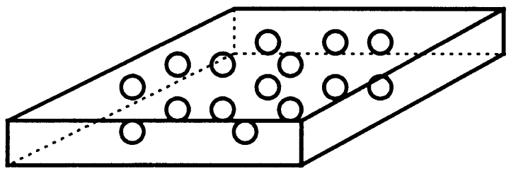
Schematic of Particle Reinforced composite [Ref]
Flake Reinforced Composites: Flakes can’t be easily orientated and there aren’t many materials that can be used. Glass, mica, aluminum, and silver are examples of common flake materials.
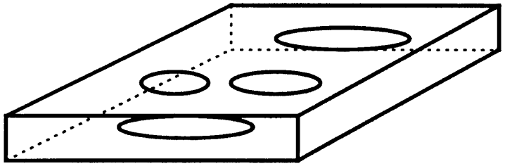
Schematic of Flake Reinforced composite [Ref]
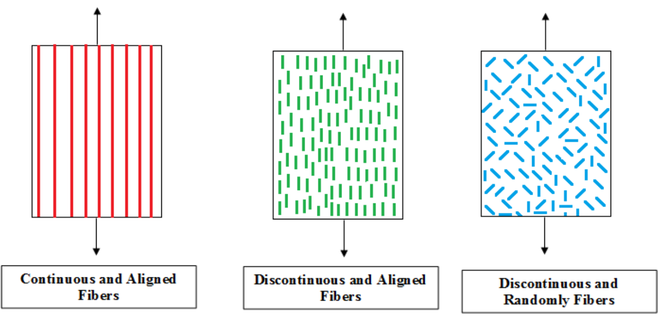
Fiber Reinforced Composites: Regarding the size of the fiber, fiber-reinforced composites are divided into two categories:
Schematic of Fiber Reinforced Composite [Ref]
continuous and discontinuous. When referring to fibers that are as long as the composite material, the phrase “continuous-fiber-reinforced composite” is used, whereas “discontinuous-fiber-reinforced composite” is used to describe fibers that are relatively short in contrast to the size of the composite material. The fibers could be distributed aligned or at random in the discontinuous type. See the figures below to understand better. Composite simulation
The continuous type could be aligned unidirectional, bidirectional, or even woven.
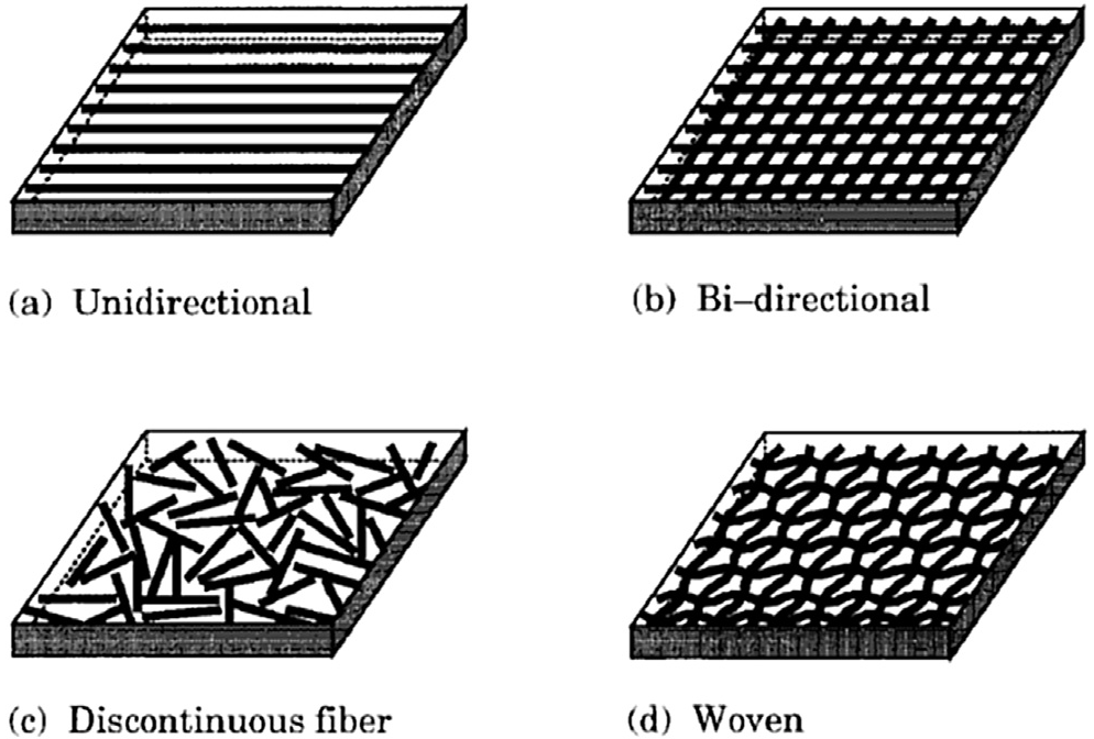
Different types of fiber-reinforced composites [Ref]
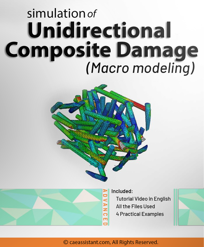
In unidirectional composites, all fibers are aligned in a single direction; therefore, despite having high mechanical strength, unidirectional fiber-reinforced composites are weaker under transverse tension than they are under longitudinal tension. So, they shouldn’t be used for parts that need a significant anisotropic strength (strength in all directions). When front-to-back strength is crucial, unidirectional reinforcement is the best option. For instance, unidirectional carbon fiber is frequently used as reinforcement in long, tubular structures that can only move forward and backward, such as boats, rockets, and airplanes. for getting more valuable insights about unidirectional composite damage read the related post.
In bidirectional composites, all fibers are aligned in two unique directions. In this type ultimate strength is low, but occurs in two unique directions. Reduced ultimate strength occurs when characteristics are constant in all directions and the direction of the fibers becomes more statistically varied across the composite. (composite simulation is described in the next sections)
The discontinuous fiber-reinforced composite may also be referred to as the short fiber-reinforced composite. Hence, when short (chopped) fibers are combined with the matrix, they create a composite known as short fiber reinforced composite. Depending on the intended application, the fibers within this composite may be arranged in either an aligned or random manner within the matrix.
Woven composites are net-shaped composite structures that are fully interconnected by their yarns. Like a piece of cloth, the yarns are weaved together as warp and weft to create a 3D composite structure.
I know you might get confused with all these categories. But take a deep breath and look at the pictures again. The pictures always help to better understand something.
Now, it’s time to see some practical examples of Fiber-Reinforced Composites (FRCs):
Glass Fiber Reinforced Polymer (GFRP), Carbon Fiber Reinforced Polymer (CFRP), etc. The most common CFRP composite productions are Tennis rackets, golf clubs, softball bats, hockey sticks, and archery arrows and bows. Some applications of GFRP are in Electronic enclosures, Water pipes or drain coverings, and Sporting equipment such as kayaks, Helicopter rotor blades, wind turbine blades, etc.
Nanocomposites: Advanced composite materials typically have microscale components (10–6 m). The majority of the qualities of the resulting composite material are superior to those at the microscale, thanks to the use of nanoscale components. However, some nanocomposites’ qualities, like toughness and impact strength, can actually worsen.
Nanocomposite films have improved qualities including elastic modulus and transmission rates for water vapor, heat distortion, and oxygen in packaging applications for the military, among other uses.
Composite Laminates and Stacking Sequences
So far, we’ve looked at composites based on their matrix and reinforcement. But in real-world engineering, most structures are not made of just one layer. Instead, they are built from laminates—multiple layers of composite plies stacked together in different orientations.
A composite laminate is an assembly of fibrous composite layers bonded together. Each ply can contain:
-
Unidirectional fibers (strong in one direction).
-
Short fibers.
-
Woven or braided fibers embedded in a matrix.
By changing the stacking sequence (the order and orientation of plies), engineers can tailor properties such as:
-
In-plane stiffness.
-
Bending stiffness.
-
Strength.
-
Coefficient of thermal expansion.
This is why laminate modeling is central in composite simulation and analysis, especially in tools like Abaqus composite modules.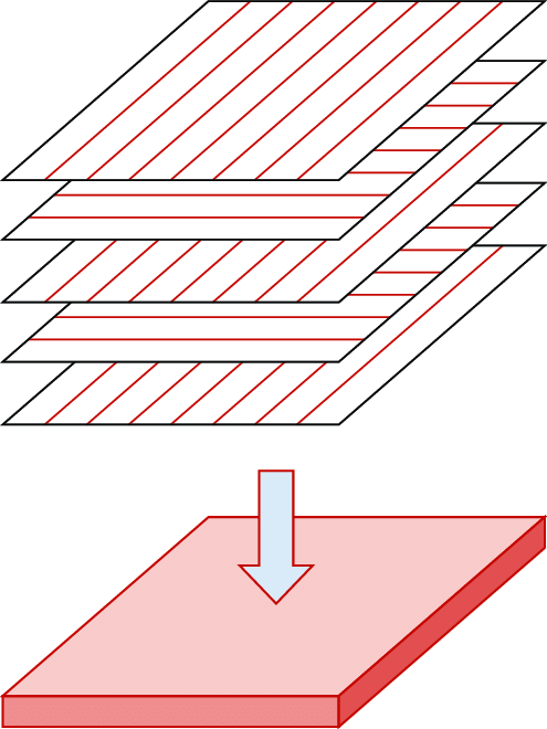
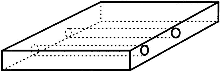
Composite laminate [Ref]
composite laminate specimen
Hybrid and Tailored Laminates
Not every layer has to be the same. By combining different materials or fiber orientations, engineers can create hybrid laminates. These laminates can exhibit:
-
Anisotropic properties → properties vary with direction.
-
Orthotropic properties → properties repeat in two orthogonal directions.
-
Quasi-isotropic properties → nearly isotropic in-plane behavior, achieved by carefully orienting layers (often ±45°, 0°, 90°).
Interestingly, the stacking order itself can create coupling effects—where in-plane loads cause out-of-plane deformations (and vice versa). That’s why laminate theory is so important in composite analysis.
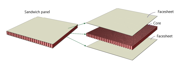
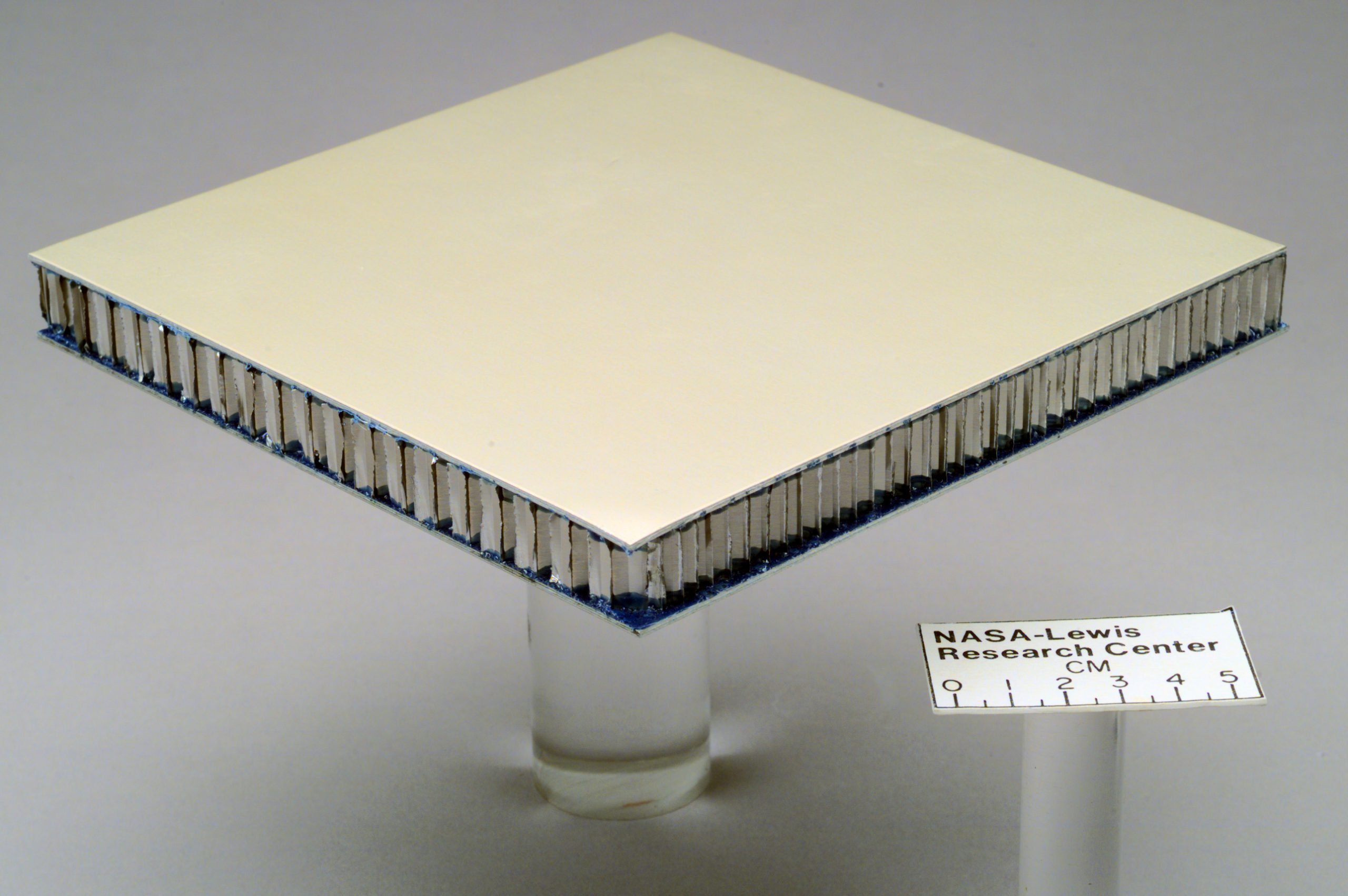
Sandwich Structures
Another special type of laminate is the sandwich composite. This design has a lightweight core (often foam or honeycomb) bonded between two strong facesheets.
Key advantages:
-
Extremely high bending stiffness-to-weight ratio.
-
Lightweight, yet strong enough for structural loads.
-
Core keeps weight low while facesheets carry the bending stresses.
Applications of Laminated Composites
Laminates are everywhere in modern engineering:
-
Aerospace → aircraft wings, fuselages, and tail sections, where high strength and low weight are critical.
-
Automotive and transport → lightweight body panels and structural reinforcements.
-
Construction → building envelopes, prefabricated wall panels, clean rooms, and energy-efficient facades.
-
Packaging → polypropylene honeycomb boards, fluted polypropylene sheets, and protective casings.
Their versatility, strength, and lightweight performance make them a natural fit for industries where mechanical efficiency and design freedom matter.
Composite laminates allow engineers to customize performance by stacking layers in different orientations. Sandwich panels take it further by combining facesheets and cores for maximum bending stiffness at minimum weight.
This is why in Abaqus composite simulations, you’ll see a lot of focus on laminate layups, stacking sequences, and sandwich structures—because that’s how real components are designed in aerospace, automotive, and construction.
Why Do We Simulate Composites?
Composite simulation and composite analysis let engineers explore designs faster and safer than relying on physical tests alone. Simulating composites is not optional. It saves money and time. It also reduces test cycles and helps you find failure modes before you build parts.
Physical tests cost a lot. They require tooling, specimens, lab time, and repeat runs.
By contrast, a well-set-up finite element model lets you test many design variants quickly.
Therefore, teams use FEA to cut prototype counts. They reduce test time and materials.
Practical notes:
- Start with simple models to screen options. Then refine the most promising designs with higher-fidelity analysis.
- Use simulation to check manufacturability (e.g., fiber draping, residual stresses) before committing to tooling. This step avoids expensive late changes.
Multiscale Composite Modeling: Micro, Meso, and Macro Approaches
Composites are not uniform like metals. Their fibers, matrix, and interfaces behave differently depending on the scale we study them. That’s why engineers use multiscale composite modeling—to connect the microscopic behavior of fibers and matrix with the macroscopic behavior of full structures. Each scale answers different design questions, and together they give a complete picture.
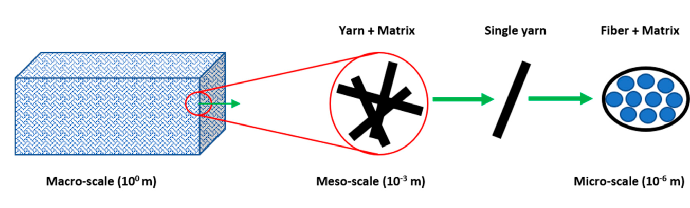
Microscale: Fiber and Matrix Level (10⁻⁶ m to 10⁻³ m)
At this scale, we look at individual fibers, the matrix, and their interface. The goal is to understand how these constituents work together. Microscale modeling helps us:
-
Predict effective material properties like stiffness or strength.
-
Study fiber–matrix debonding and micro-cracking.
-
Capture how defects (voids, poor bonding) affect performance.
This level is detailed but also computationally expensive, so it’s often used to generate material data for higher-level models rather than to simulate large parts directly.
Mesoscale: Ply and Laminate Level (10⁻³ m to 10⁻² m)
Here, the focus shifts from individual fibers to plies and laminates. A ply can have fibers aligned in one direction, woven fabrics, or even hybrid reinforcements.
Mesoscale modeling helps us:
-
Study how plies interact in a laminate.
-
Predict delamination between layers.
-
Investigate the influence of stacking sequence on stiffness and strength.
This is the scale where progressive damage modeling often starts, capturing cracks that grow within or between plies.
Macroscale: Structural Level (10⁻¹ m and above)
At this level, we model the entire composite structure—for example, a wing, a car hood, or a wind turbine blade. Instead of fibers or plies, the material is treated as an equivalent “homogenized” material with effective properties derived from the lower scales.
Macroscale modeling helps us:
-
Perform full structural analysis (strength, stiffness, buckling).
-
Study global failure modes like large delaminations or collapse.
-
Optimize designs by running simulations faster than with lower-scale detail.
This is the most common scale used in FEA software like Abaqus, Ansys, or Altair, especially when simulating large industrial structures.
Common Challenges in Composite Simulation
Composite simulation is powerful. However, it also brings challenges. The main ones are anisotropy, delamination, and high computational cost. Let’s unpack each.
1) Anisotropy (directional behavior)
Composites are direction-dependent. So you must define fiber orientation and ply angles correctly.
Wrong orientation gives wrong stiffness and wrong failure predictions. Thus, accurate layup definition is essential.
2) Delamination and interlaminar damage
Layers can separate under through-thickness loads, impact, or cyclic loading.
Modeling delamination needs cohesive elements, contact definitions, or dedicated fracture models. These add complexity and runtime.
3) High computational cost
Fine microscale RVE models and 3D solid elements are expensive.
Full-scale, high-fidelity models need lots of CPU time and memory.
Engineers balance fidelity vs. cost by using homogenization, shell approximations, and submodeling.
4) Other practical challenges
Finding reliable material properties for plies and interfaces.
Representing manufacturing effects (resin pockets, voids, fiber waviness).
Predicting fatigue life under complex loading.
Tips to manage challenges:
Use simplified models for early design phases.
Add local 3D detail only where damage or stress concentration matters.
Validate models against a few targeted tests to build confidence.
Composite Simulation Software: Abaqus, Ansys, Altair, and Open-Source Tools
Choosing the right tool depends on your goals, budget, and team skillset. Below is a short practical guide. Use it as a decision checklist.
Abaqus (SIMULIA): strong in advanced composite analysis
-
Excellent for layered composites, nonlinear behavior, and advanced failure criteria (Hashin, Puck, Tsai-Wu).
-
Good support for cohesive elements and delamination modeling.
-
Widely used in academia and industry for detailed Abaqus composite workflows.
Ansys: integrated multiphysics and industry workflows
-
Strong in coupling structural, thermal, and manufacturing simulations.
-
Useful for full-product workflows where composite parts interact with other systems.
-
Good commercial support and broad multiphysics capabilities.
Altair: optimization and manufacturability focus
-
Emphasizes optimization, lightweighting, and manufacturability checks (forming, drape).
-
Good when you need to couple design optimization with composite performance.
Open-source options (e.g., CalculiX, PrePoMax, MOOSE)
-
CalculiX supports many FEA tasks and uses an Abaqus-like input format. It can be extended for composite work and is used in research and education.
-
These tools lower cost but may require more manual setup and scripting. They also have smaller ecosystems than the big vendors.
Which to pick? Quick rules-of-thumb
-
If you need deep, validated composite features (delamination, ply by ply failure), pick Abaqus or Ansys.
-
If you need optimization and manufacturability checks, include Altair in your evaluation.
-
If budget is tight or you want to script and customize heavily, evaluate CalculiX + pre/post tools.
Key Concepts in Composite Simulation
Before jumping into a composite simulation, it’s important to pause and look at the fundamentals. Unlike metals, composites bring extra layers of complexity. You need to decide:
-
What type of composite are you modeling?
-
At which scale are you working—micro, meso, or macro?
-
Do you expect damage, fatigue, or just elastic behavior?
-
Which failure criteria should guide your analysis?
These questions shape your entire simulation strategy.
In this section, we’ll walk through the core ideas every engineer should know before running models:
-
Failure criteria like Tsai-Wu, Hashin, and Puck, and when to use each.
-
Damage simulation, covering delamination, impact, and blast loading.
-
Fatigue simulation, to predict how composites behave under repeated loading.
Think of these as the foundation stones for accurate and reliable composite analysis. Once you understand them, your simulations in tools like Abaqus composite modules will be far more effective.
Failure Criteria – Tsai-Wu, Hashin, Puck
One of the first challenges in composite simulation is deciding how to define failure. Unlike metals, composites fail in multiple ways—fiber breakage, matrix cracking, or delamination. That’s why different failure criteria exist, each with its own strengths.
-
Tsai-Hill & Tsai-Wu Criteria
These are the “classics” in composite analysis. They work well for a quick estimate of when a laminate will fail under combined stresses. Tsai-Wu improves on Tsai-Hill by including interaction terms for tension and compression.
👉 If you want a step-by-step explanation with examples, check our guide on Tsai-Hill and Tsai-Wu Criteria. -
Hashin Criterion
Hashin goes a step further by distinguishing between fiber failure and matrix failure. That makes it more accurate when predicting progressive damage in an Abaqus composite model.
👉 See our full breakdown of Hashin Failure Criteria.
-
Puck Criterion
Puck is known for handling inter-fiber failure (IFF) very well. It can predict delamination and transverse cracking more realistically than many other models. However, it is also more complex to implement.
👉 Read our detailed tutorial on Puck Failure Theory.
Each of these criteria has pros and cons, and the “best” one depends on your application. In practice, many engineers start with Tsai-Wu for simplicity, then move to Hashin or Puck as they need more accuracy.
Need help choosing the right criterion? Contact our support team anytime via email, live chat, or WhatsApp—we’ll guide you based on your specific project.
-
Tsai-Wu → “Quick check”
-
Hashin → “Fiber vs Matrix”
-
Puck → “Delamination focus”
Damage Simulation: Delamination, Impact, Fiber cracking, etc.
In composites, damage doesn’t look like it does in metals. Instead of yielding, you may see micro-cracks in the matrix, fiber breakage, or delamination between layers. These local damages can quickly grow, leading to sudden failure. That’s why damage simulation is a key step in composite analysis.
-
Delamination
One of the most common and dangerous failure modes. Delamination reduces stiffness, changes load paths, and can lead to catastrophic collapse. Simulation helps you predict where and when it will occur. -
Impact
Low-velocity impacts (like tool drops) and high-velocity impacts (like bird strikes in aerospace) can create hidden damage. Composite FEA allows engineers to study the extent of fiber breakage and matrix cracking without destructive tests. -
Blast and Extreme Loads
In defense and aerospace, composites may be subjected to explosions or blasts. Here, modeling energy absorption and progressive failure is crucial for safety.
If you’d like a step-by-step walkthrough on how to model these damages in Abaqus, check our detailed guide on Composite Damage.
Fatigue Simulation: Predicting Lifetime Under Cyclic Loads
Composites are strong, but what happens when they face millions of load cycles? Unlike metals, which often show a clear fatigue crack growth pattern, composites fail in more complex ways. Fibers and matrix wear out differently, leading to multiple failure modes. That’s where fatigue simulation becomes essential.
-
Why fatigue matters
In aerospace, automotive, and wind energy, components face repeated loads every day. Even if a part doesn’t fail instantly, small damages accumulate over time. Simulating fatigue helps predict service life and prevent unexpected failures. -
Unique fatigue behavior in composites
Unlike metals, composites do not have a single, predictable fatigue limit. Instead, fatigue depends on fiber orientation, loading type, and material architecture (short fibers, woven, unidirectional, etc.). -
Applications
Fatigue analysis helps engineers decide whether a composite structure can survive its design life—whether it’s an airplane wing, a car chassis, or a wind turbine blade.
For a detailed example, including how to handle short fiber composites, check our full guide on Composite Fatigue Simulation.

Abaqus Composite Simulation Step by Step
Learning composite simulation can feel overwhelming at first. There are many material properties, layups, and analysis types to consider. The good news is that if you follow a structured workflow, the process becomes much more manageable.
In this section, we’ll give you a quick overview of the main steps for running a composite analysis in Abaqus. You’ll see what data you need to collect, how to set up your material and layup, and how to run and interpret your results.
We’ll also cover alternatives if you don’t have access to Abaqus, so you can still practice with other tools.
but let’s make an overview of the steps we need to make for a Abaqus composite simulation:
Step 0: Collecting Composite Material Data
Before you even open Abaqus, you need the basics: elastic constants (E1, E2, G12, ν12), ply thickness, and strength values. Without accurate data, your composite simulation will never match reality.
Step 1: Defining Composite Material Properties in Abaqus
Once the data is ready, the first step is defining the orthotropic material properties in Abaqus. This includes elastic properties and strength values that will later be used in failure criteria.

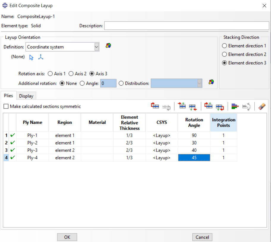
Step 2: Creating a Composite Layup
Here you build the laminate by defining the ply sequence, orientation, and thickness. This step is crucial since fiber direction directly affects stiffness and strength.
Step 3: Applying Loads and Boundary Conditions
Next, you set up the loads (tensile, shear, bending, impact) and boundary conditions. Choosing realistic conditions ensures your simulation reflects the actual structure.

Step 4: Choosing the Right Analysis Type
Composite analysis can vary: static loading, buckling, impact, or fatigue. Abaqus allows you to select the proper analysis type depending on the problem.
Step 5: Running and Interpreting Results
After running the simulation, you’ll examine stresses, strains, and failure indices. This step is where failure criteria like Tsai-Wu or Hashin come into play to evaluate if and where the laminate fails.

Step 6: Validating with Experiments
Simulation results must be validated. Common validation tests include tensile, shear, or delamination tests like DCB and ENF. This ensures your FEA model represents physical behavior.
Alternative Tools if You Don’t Have Abaqus
-
Commercial: Ansys Composite PrepPost, Altair OptiStruct
-
Open-source: CalculiX, Code_Aster
👉 This is just a quick overview. For a complete step-by-step walkthrough with images, settings, and examples in Abaqus, download our FREE Composite Simulation Tutorial (PDF) here:
Recap
We’ve covered a lot of ground in this blog. Let’s quickly go over the key points:
-
What are composites? → We looked at why composites are used, their advantages and disadvantages, and how they behave differently from metals.
-
Types of composites → Classified by matrix, reinforcement, and laminates/stacking sequences.
-
Why simulation matters → Composite analysis through FEA saves time and cost compared to experiments, but it comes with challenges like anisotropy, delamination, and computational demand.
-
Key concepts in simulation → We touched on failure criteria (Tsai-Wu, Hashin, Puck), damage and fatigue simulation, and multiscale modeling approaches.
-
Step-by-step workflow → From material data collection to validation, plus alternative software if Abaqus isn’t available.
The main takeaway: Composite simulation is complex but manageable if approached step by step. It requires understanding both the materials and the modeling techniques.
Other helpful references
-
Altair Composites: Industry applications and solutions.
-
Ansys Blog: Composite design challenges.
-
Abaqus Composite Simulation Package: Add-on tools for composite FEA.
-
Academic article on composites: For those who want to dive into the science.
You can get all in our Composite Simulation Course in Abaqus.


One Response
Hello, thank you for this useful article. I learned a lot of good points about the analysis of composite materials.
Do you recommend me any training package for the analysis of chopped composite materials?
thank you