


What is additive manufacturing or 3D printing?
The process of building a three-dimensional object from a CAD model or digital 3D model is known as additive manufacturing or 3D printing. In an additive process, an object is made by adding layers of material one after another until the product is made. This process can be done via several methods in which material is joined, deposited, and solidified under computer control. The materials being added together could be made of plastics, liquids or powder grains being fused, etc. 3D printing Abaqus modeling is fully described in this training package.
Did you know we have 3D printing for composite materials as well?! You can learn all about it in our course: “3D Printing Composites with Continuous fiber Reinforced Structures: Design, Fabrication, and Applications“. The syllabus of this course.
Abaqus Additive manufacturing or Abaqus 3D printing simulation
Why do we need Abaqus additive manufacturing simulation? Because of the same reasons, we do other simulations. Checking if there is any residual stress, checking temperature and thermal conditions, deflection in the model, etc. Moreover, to see if the machine’s settings suit our model’s conditions before printing to avoid unnecessary costs. Conditions like material properties, temperature, etc.
This 3D printing Abaqus training package will teach you to do this simulation with two methods: The first method is based on the use of subroutines and Python scripting and was done by a team with the goal of coding all the steps of 3D printing, and the second method uses ADM plug-in developed by Dassault Systemes company to simulate 3D printing process.
Method 1: Using Scripting and Subroutines
In this method, we have three coding files. One is a Python script, and the others are USDFLD and DISP subroutines.
Python script: This script will do everything for us. Creating material properties, sections, interactions, basically anything that must be done in the Abaqus GUI, the code will do it for us. You just need to run the script, enter some inputs, and wait until the simulation is completed. About the modelling, you must create your model in CAD software or the Abaqus itself; then layer the model and save the layers as “igs” files. When you run the script, one of the inputs that you should insert is the directory path of these files.
USDFLD subroutine: With this subroutine, we calculate the elasticity properties because in the 3D printing process, the elasticity is not constant and changes during the process. The formulas used to calculate the elasticity in this tutorial are according to these references: “Rapid Prototyping & Manufacturing, Fundamentals of
Stereolithography“, “Curl Distortion Analysis During
Photopolymerisation of Stereolithography Using Dynamic Finite Element
Method“.
The formulas and equations are explained in the tutorial video completely. Of course, you can apply your own equations and assumptions to calculate the elasticity.
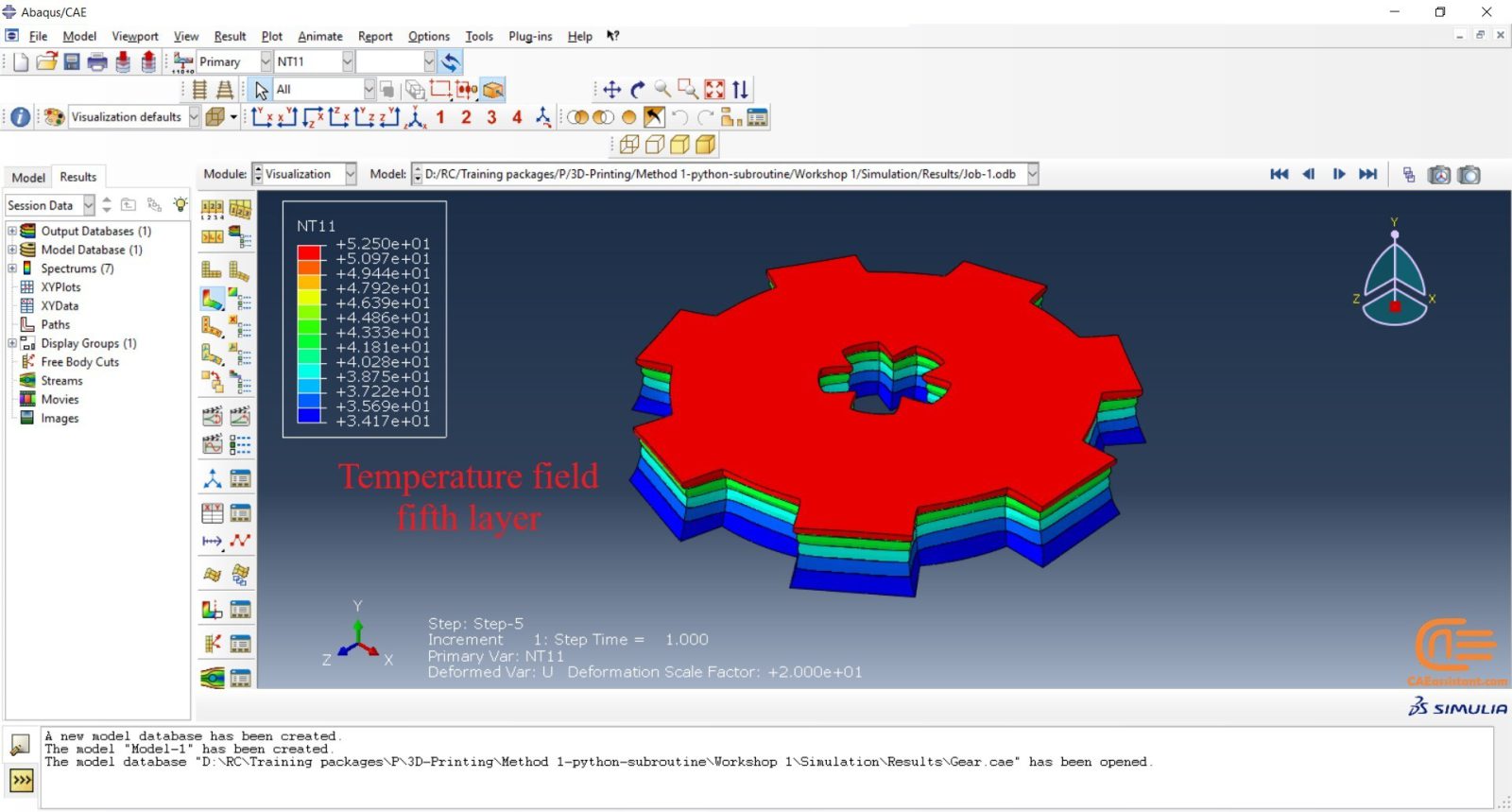
DISP subroutine: The temperature changes during the process will be calculated by the DISP subroutine. The formulas used to calculate the temperature changes are based on our assumptions. You can apply yours based on any references you see fit.
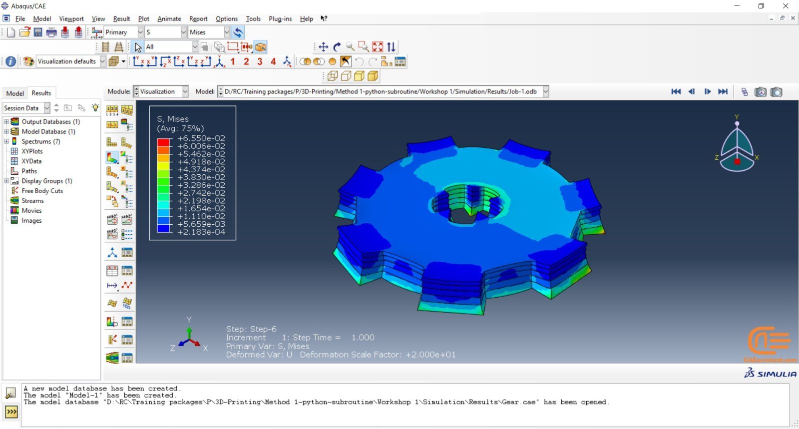
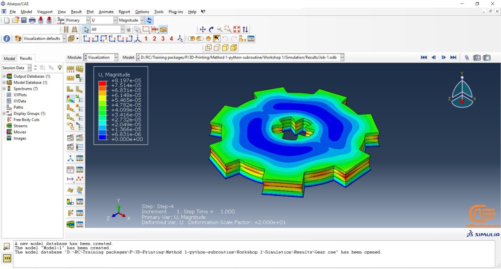
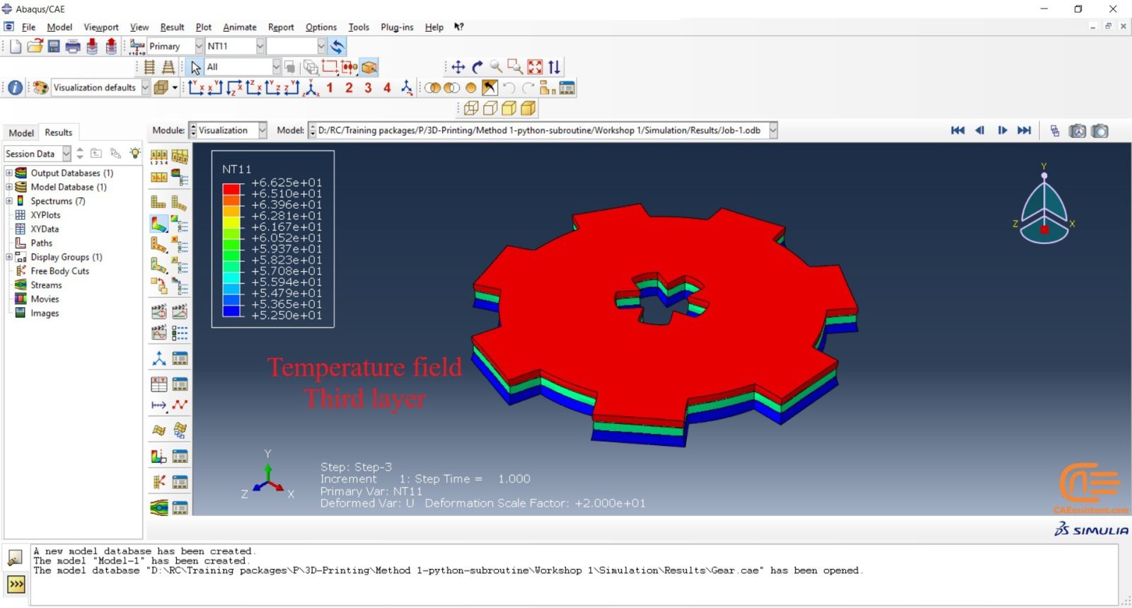
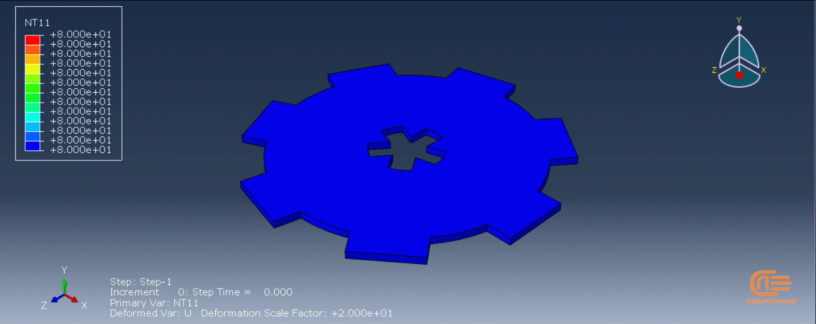
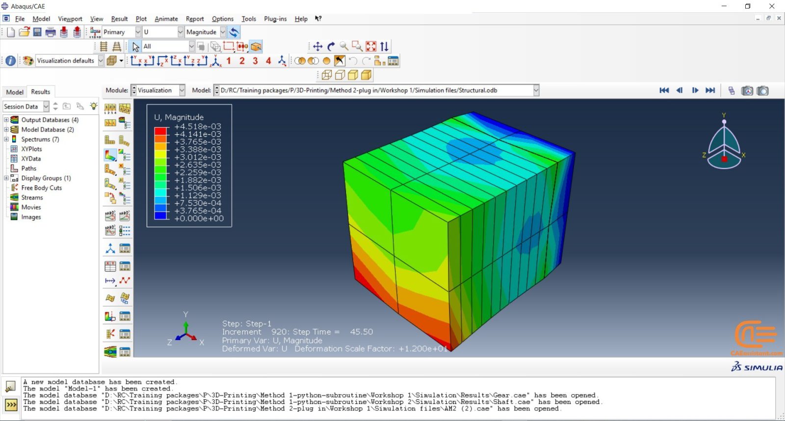
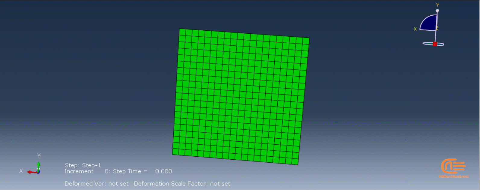
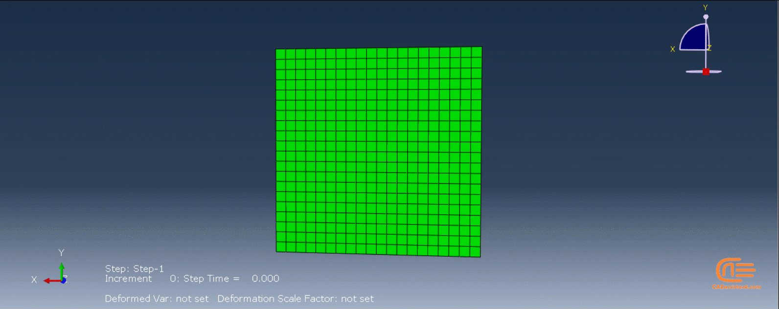
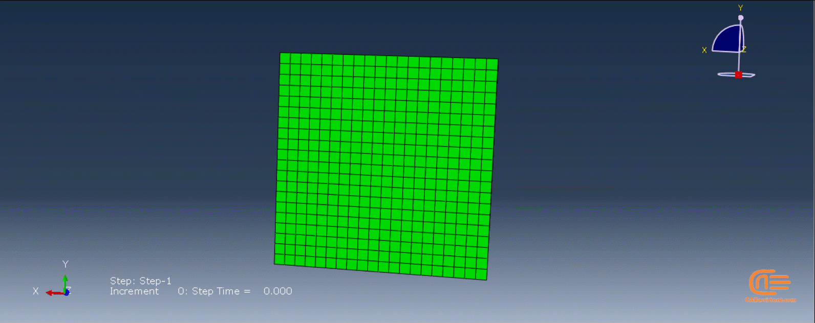
There are two workshops for this method, each using a different version of the python code. The first workshop simulates the 3D printing of gear, and this version of the python code used in this simulation is for uniform models. By uniform model, we mean that all layers must be identical if you layer the model. In this workshop, you have to create just one layer of your model in CAD software or the Abaqus itself and save it as an “igs” file; then, when you run the code, you must enter the directory path of the file and some inputs and wait till the job is completed. (3D printing ABAQUS)
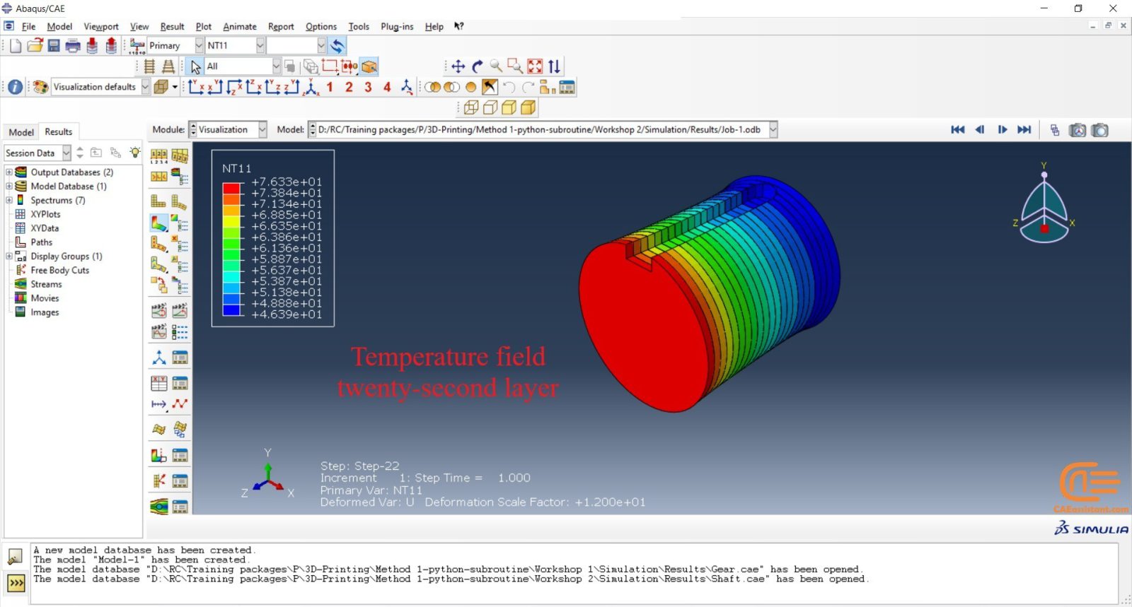
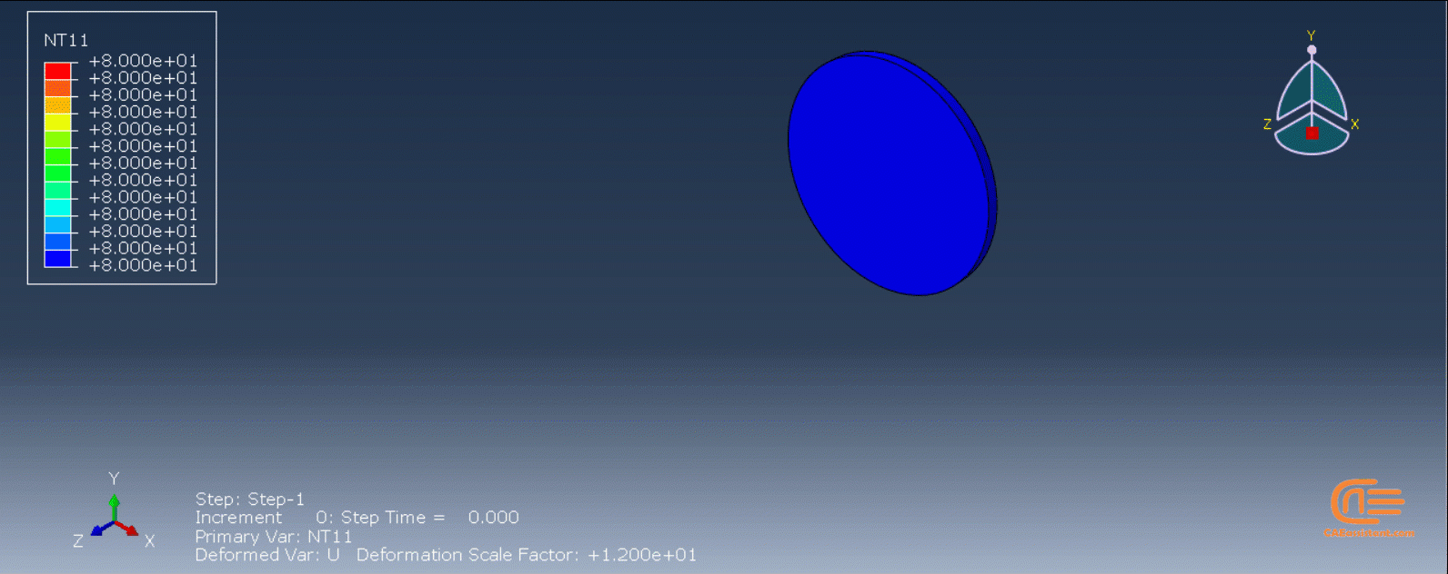
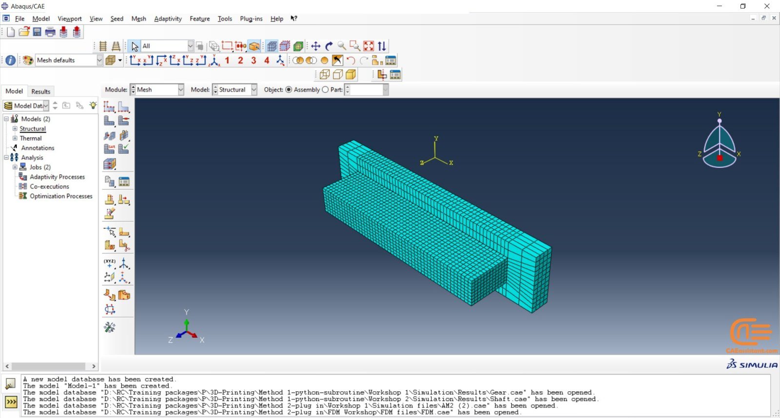
In the second workshop, an industrial shaft will be simulated. There are no differences in the subroutine files except for some of their inputs. The version of the python code used in this simulation is for nonuniform models. This means the layers of the model are different. Therefore, we need to have all the layers as “igs” files. After the script is run, we insert the directory path of these files along with other inputs and wait till the job is completed. In this version of python code, there would be other differences as well, which will be explained in the video.
Note: Did you know you can use topology optimization in for a 3D printing part? Interesting, isn’t it? Lucky for you we have course for that called: “Advanced Space–Time Topology Optimization in Multi-Axis Additive Manufacturing“.
Workshop 1: 3D printing Abaqus simulation of Gear with DISP, USDFLD and Python scripting (Same cross-section)
In this workshop, first, the geometry of the model is explained. Next, the difference between continuous and discontinuous layers is discussed, which is an important issue regarding using the Python script for these kinds of examples. Then, material properties with all their equations and detail are explained, and these properties are defined using the USDFLD subroutine. Next, the boundary conditions are explained. After that, the temperature changes and their relations are discussed, which is applied to the model using the DISP subroutine. Finally, after explaining how the Python code and subroutines are written and work, the simulation will be done, and the results will be discussed.
Workshop 2: 3D printing Abaqus simulation of shaft with DISP, USDFLD and Python scripting (non-uniform section)
In this workshop, like the previous one, the model’s geometry is explained at first. Next, the model layering is presented. All other stages would be like the previous workshop. The only differences are in the model’s geometry, Python code, and layers; the differences are because this model has a non-uniform cross-section.
Enroll for this advanced course to complete you education in Additive manufacturing:
“Machine Learning for Predicting Fatigue Properties in Additive Manufacturing Course”
Method 2: Using AM Modeler plug-in for additive manufacturing
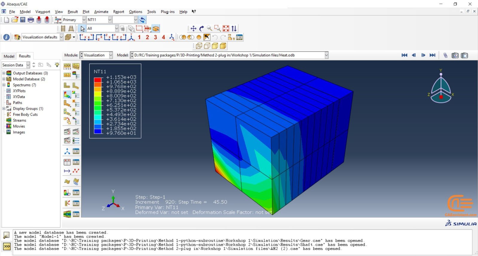
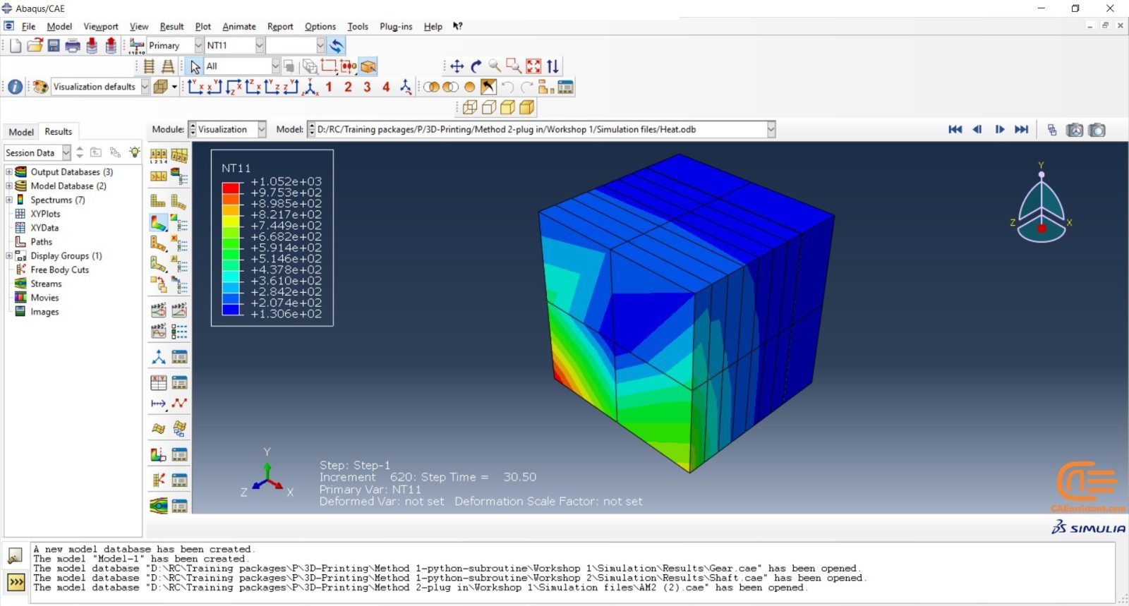
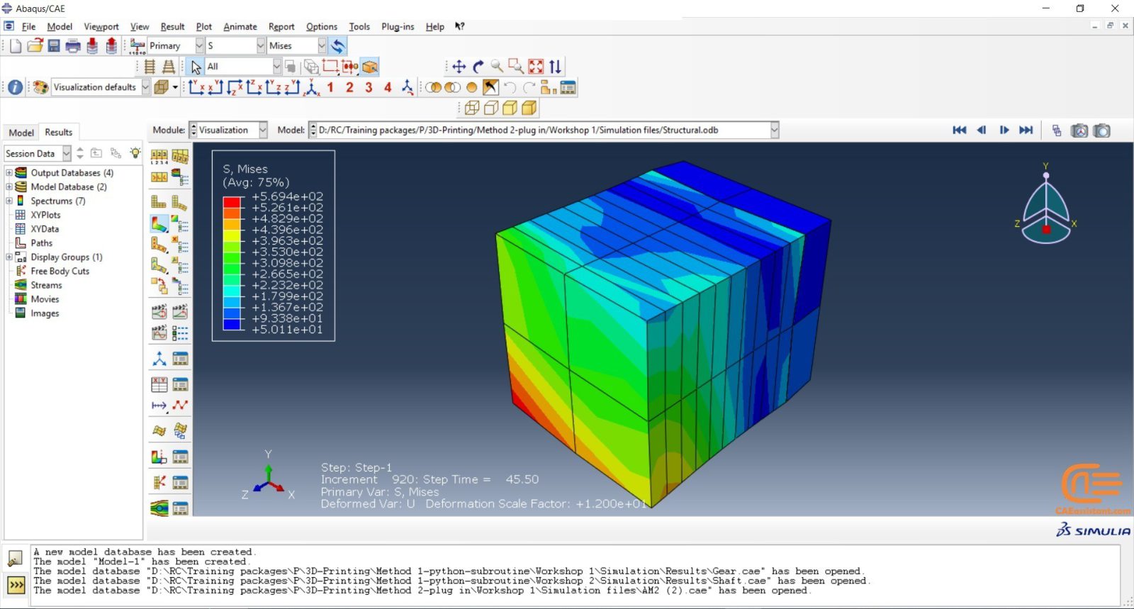
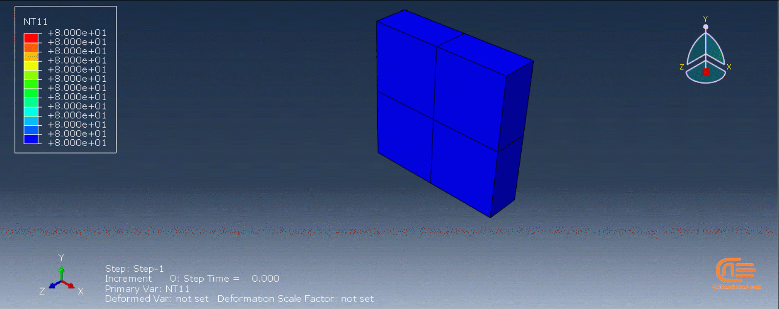
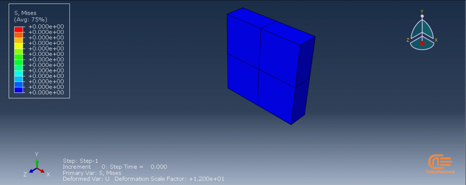
The “AM Modeler” plug-in is a user-friendly interface for Abaqus additive manufacturing simulation that allows users to simulate 3D printing with minimal risk of errors. Unlike Python scripting or coding, this plug-in only requires users to input the necessary data, create a job, and start the simulation. The plug-in simulates 3D printing using two methods: eigenstrain and thermomechanical. Each method has different process types that users can choose from based on their specific needs. The eigenstrain method has two process types: trajectory-based and pattern-based, while the thermomechanical method has four process types: trajectory-based powder bed fabrication, pattern-based powder bed fabrication, laser direct energy deposition, and fusion deposition modeling. This training package focuses on the thermomechanical method.
The thermomechanical approach involves a thermal-stress analysis of an additive manufacturing process, which is performed sequentially. Initially, a heat transfer analysis is conducted, followed by a static structural analysis that utilizes the temperature fields obtained from the thermal analysis. The simulation allows for precise control over processing conditions in both time and space, resulting in a thorough and realistic solution. However, as time and spatial (mesh) resolution increase, the simulation becomes computationally expensive.
The heat transfer analysis must simulate the progressive material deposition, progressive heating of deposited material, and progressive cooling of the printed part. The stress analysis is driven by temperatures from the heat transfer analysis, and progressive material deposition methods comparable to the heat transfer analysis can be applied. Temperature-dependent material properties can be used for precise stress results.
Note: 3D printing can be used to produce complex components quickly and cost-effectively, allowing for more customization and reduced lead times, right? SO, it can be a great help in Smart manufacturing! But what is smart manufacturing anyway? Do not worry because we have a complete course of it: “Smart Manufacturing Course.”
Workshops of the second method
There are three main workshops for this method: “Sequential thermomechanical analysis of simple cube one-direction LPBF 3D printing using trajectory-based method with AM plug-in”, “Abaqus 3D printing simulation with Fusion deposition modeling and Laser direct energy deposition method with AM plug-in”, and “Material Removing with AM plug-in”. These workshops are done with two versions of the AM Modeler: an older version and a newer version; the first workshop (LPBF) is done with the older version, and the other two with the newer version. Why two versions? It’s because of you to learn how to work with them in case you have each of them.


11 reviews for Abaqus 3D Printing Simulation Course
cardoso –
This course is great for beginners. Taught me all the basic tools needed in for 3d printing simulation. The projects were fun to follow along and the explanations were clear.
sojong –
The 3D Printing courses was challenging and Fun. It took a lot more time for me than estimated: Great Course!
rira.sam –
Exceptional teaching course for getting introduced to simulate 3d printing with abaqus. By the end of this course I absolutely was able to create my own designs for 3d printed functional objects
marin.Hail –
This course is quite good and detailed. One thing I might add is that put some documents on the topics like some review papers or other documents.
Sophia-rotu –
I am very satisfied with this 3D printing Abaqus training package. The tutorials are comprehensive and cover everything from basic concepts to advanced simulation techniques.
Théo-mia –
hi caeassistant team, I want to say that the first method, which uses scripting and subroutines, is a great option for those who want to have more control over their simulation and customize it according to their needs also the tutorial videos explain everything in detail and make it easy to follow.
Thank you for being professional.